

A production line may run a wide tray in the morning and a narrow, taller component in the afternoon. An air knife that reaches the full width of the tray may sit too far from one product or too close to the other. Increasing conveyor speed introduces another change: each surface passes through the air stream more quickly.
Selecting an Air Knife means matching coverage, access, and treatment time to the products that will actually run. Start with the surfaces that need treatment, translate their positions into a coverage requirement, and then check that the proposed arrangement works at the required production rate. Air supply selection follows that layout.
This guide focuses on conveyor-based surface-water removal. The same dimensional checks can help with cleaning or cooling, but those processes need their own acceptance criteria. A dry-looking surface is not a substitute for a cleanliness measurement or a required final temperature.
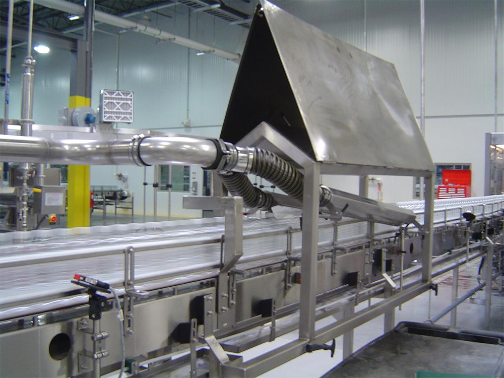
Before measuring the conveyor, specify what the next process needs. A bottle may only need a dry label area. A washed component may need its underside and recessed features cleared before packaging. Those are different treatment tasks, even if the products have similar overall dimensions.
Record the liquid being removed, where it collects, the incoming condition, and the required condition after treatment. If the requirement is no visible droplets on an agreed surface, write that down. If a downstream process has a measured moisture limit, use that limit and its test method instead.
Then identify the installed orientation. Mark the travel direction and show which faces are exposed. Include guide rails, fixtures, and supports on the sketch. A knife selected by width alone may still have no useful access to the wet surface behind a rail.
ACI lists target object dimensions, required results, production speed, and available installation space among its system-selection questions. These inputs belong in the initial application brief rather than being left until installation.
For an overhead knife aimed at a flat upper face, begin with the width of the target surface across the conveyor. For a side-mounted knife, the relevant dimension may be the height of the surface. Product length in the direction of travel is a separate input; it does not normally determine the length of a transverse overhead knife.
Measure where the product can actually travel. A centered, guided part has a different coverage requirement from a part that can move sideways or rotate. For several lanes, measure the outer limits of the occupied lanes, including allowed movement. Check whether one continuous outlet or separately positioned outlets better matches that arrangement.
Keep three dimensions separate in the supplier drawing: overall knife body length, active outlet length, and verified coverage at the product surface. End plates and fittings occupy space, and airflow performance at the target cannot be established from body length alone.
Consider a hypothetical 420 mm wide product on a 600 mm belt. If the product remains square to the travel direction but its center can shift 15 mm to either side, the target spans a 450 mm lateral envelope: 420 + 15 + 15.
That calculation defines the area requiring treatment. It does not prove that a nominal 450 mm air knife will perform adequately. Ask the supplier to confirm usable coverage across that envelope at the intended distance, mounting angle, and air supply. Any additional allowance should follow the installation tolerances and coverage evidence, not an arbitrary percentage.
If a straight knife is mounted diagonally across the belt, check its projected width on the layout. Its physical length no longer equals its cross-belt span. Keep this plan-view angle separate from the angle at which the air strikes the surface.
For a side installation, show the highest and lowest points requiring treatment. Paxton's side-mounting instructions illustrate how knife position, product height, and mounting geometry work together. Their specified settings apply to that mounting arrangement and should not be copied as universal settings.
Ask for belt speed in metres per minute or another stated distance-per-time unit. Pieces per minute alone is not enough: the same throughput can result from different product spacing, lane counts, or belt speeds.
For equally spaced products moving without slip in one lane, conveyor speed equals product pitch multiplied by throughput. Pitch means the distance from one product's reference point to the same point on the next product, including the gap.
For example, a hypothetical single lane carrying 60 products per minute at a 0.4 m pitch travels at 24 m/min. A two-lane conveyor with the same total throughput cannot be assessed using that single-lane calculation without first establishing the throughput in each lane.
Next distinguish drying-zone travel time from direct air exposure. A product travelling through a 0.6 m zone at 12 m/min spends 3 seconds in the zone. It does not necessarily receive 3 seconds of direct blowing: the zone may contain gaps between individual air streams.
For one surface point travelling through a measured effective air-treatment band, exposure time is approximately the band width in the direction of travel divided by conveyor speed. Use consistent units.
As an illustration only, an effective band of 20 mm and a conveyor speed of 200 mm/s give 0.1 seconds of exposure. At 400 mm/s, the exposure becomes 0.05 seconds if the band remains unchanged.
The effective band is not the outlet gap. It is the region at the product surface where the airflow provides useful treatment, and it must be established for the actual installation. These calculations describe motion and exposure; they do not predict residual water or specify a required drying time.
When a speed increase causes failure, examine whether the arrangement needs another treatment position, better access, a different water-removal path, or revised air delivery. Simply increasing transverse knife length adds width coverage; it does not automatically increase treatment time along the conveyor.
With the coverage envelope and speed range defined, decide which surfaces need separate treatment. An overhead knife can address an exposed upper face. Side faces, undersides, or recessed features may require another position, a change in product orientation, or a separate targeted outlet.
Also trace where the removed water will go. If it is driven into a pocket or onto a surface already treated, extra blowing may not solve the layout problem. ACI describes shaped knives, including chevron and multi-sided arrangements, for specific surface-treatment tasks. This supports considering geometry when drainage or access limits a straight-knife layout; it does not make one shape universally preferable.
Only then total the outlets that will operate together. A longer active slot or additional knives can change the required airflow. Paxton publishes airflow per unit knife length for specified operating pressures on its own range, illustrating why length and air demand must be considered together. Those figures are product-specific and cannot be transferred to another knife design.
For a blower-fed arrangement, ask for a duty-point check that includes the knives, hoses, branches, and other flow restrictions. Paxton's matching guidance explains the relationship between Blower performance and air-delivery resistance. Motor power or a free-air flow rating alone is not sufficient evidence that the installed arrangement will meet its duty.
If the proposed layout uses compressed-air knives, request the required supply pressure and total consumption under simultaneous operation. Do not substitute blower-system figures. This is the point to verify the chosen supply, rather than purchasing it independently of the layout.
One system can serve several products when its coverage, adjustment range, air supply, and settings accommodate their individual requirements. The longest product dimension is only one part of that assessment.
Group products by treatment geometry. Similar flat parts with different widths may share a layout more easily than a flat panel and a tall, pocketed component. Product height changes the working distance from an overhead knife. Width changes the position of the side surfaces. Fixtures may also hide different areas when the part changes.
For batched production, specify adjustment ranges and repeatable settings. These might include knife height, side spacing, angle, conveyor guides, and an approved air setting for each product family. Paxton's side-mounting instructions provide a documented example of adjustable knife height and pitch.
Test the smallest and lightest products as well as the largest. The largest product may challenge coverage, while the lightest may need better support to avoid moving under the air stream. A smaller part can also be harder to dry if it has a water-trapping feature.
When large and small products arrive intermixed, manual changeover is not a solution. Assess whether one fixed arrangement works for every product, or whether detection and automatic adjustment are required. If neither option is practical, separate the product families or provide distinct treatment stations.
Do not assume that unused outlet sections can simply be blocked for a narrower product. Ask the supplier whether zoning or flow adjustment is supported and how it affects the remaining outlets and air source. Each operating configuration needs a confirmed supply condition.
QXY's published Drying-system information describes layouts based on product dimensions, surface shape, production rate, and drying requirements, including adjustable upper knife arrangements in reference configurations. These examples show possible configuration choices, not proof that one system will dry every product size.
The proposal should identify the product families, allowed positions, knife arrangement, speed range, and acceptance method. It should also state what changes between products. A drawing showing that the equipment fits is not yet evidence that it will remove the required water.
Run trials at the combinations most likely to challenge the design: the widest coverage envelope, the most difficult recesses, the greatest expected incoming water load, and the highest required speed. Test small or unstable products separately. These conditions may occur on different products, so one large sample cannot represent them all.
Inspect the agreed surfaces immediately after treatment and at the next process step where relevant. Record knife positions, air settings, product spacing, conveyor speed, and the incoming condition. For repeatability, use a defined sequence of products and a pass criterion agreed before the trial.
If a product only passes at a slower speed, record that limit. If a changeover requires repositioning, record the settings and verify them after another changeover. The approved result should tell the operator which products can run, at what speed, and with which setup.
For a QXY application review, prepare product drawings or photographs, minimum and maximum dimensions, lane layout, belt-speed range, incoming liquid condition, required result, and available installation space. Ask for the proposed coverage and adjustment ranges to be shown on the layout before confirming the knife length.
Need a custom air knife solution? Send us your application details, material requirement ,or air source type . Our engineering team will help you select the right model.

Shenzhen Qixingyuan Machinery Equipment Co., Ltd.
info@airknifecn.com
Building 8, Wanfeng Third Industrial Zone, Xinqiao Street, Bao'an District, Shenzhen, Guangdong, China


