Air Knife Drying Systems
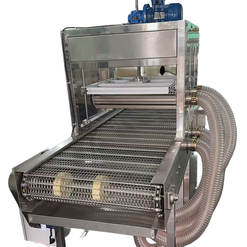
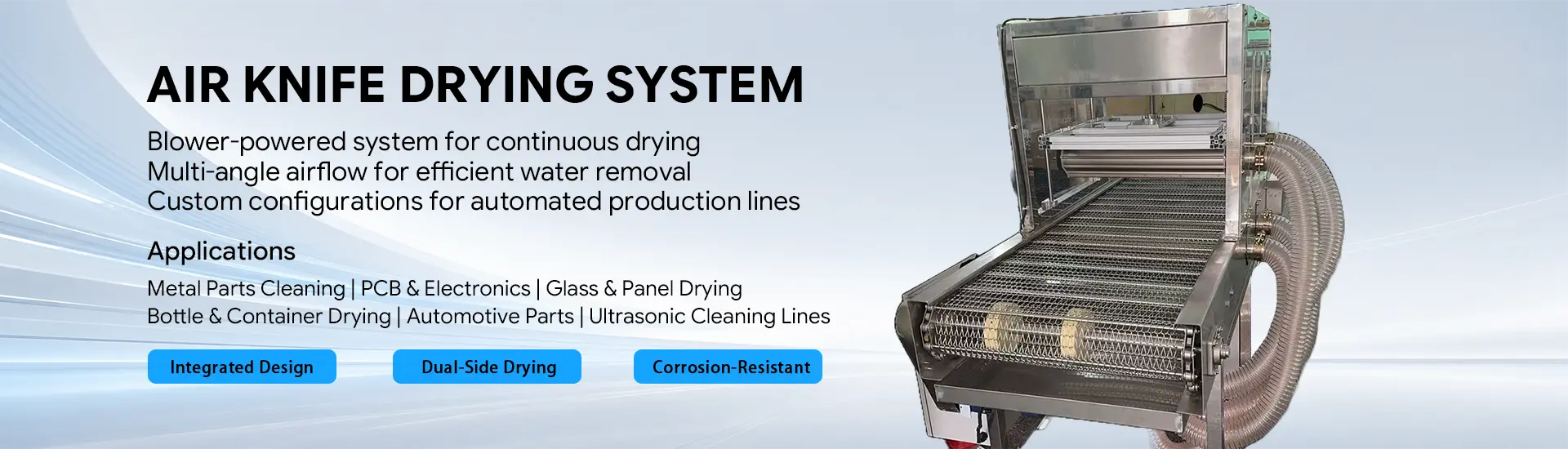
QXY air knife drying systems combine high-speed centrifugal blowers, fluid-accelerating air knives, conveyor equipment, adjustable air knife supports, splash protection, water collection and electrical controls into one integrated drying solution.
Unlike purchasing a standalone air knife, each system is designed around the actual product size, surface shape, production rate, conveyor width and required drying result. Upper, lower, side or multi-angle air knives can be arranged to remove water from flat surfaces, edges, grooves, holes and irregular components.
Conveyor speed, working width, drying-zone length, blower capacity and the number, length and position of the air knives can all be customized. Whether you need a standalone drying station or equipment integrated into an existing production line, our engineering team can recommend a suitable layout based on your products, throughput and available installation space.
A Complete Drying Process, Not Just an Air Knife
Effective industrial drying depends on more than air velocity. Air volume, pressure, air knife coverage, outlet distance, installation angle, conveyor speed, exposure time and water drainage must work together.
QXY designs the blower, air knives, conveyor and drying chamber as one coordinated system. This allows the airflow to reach the required surfaces while the conveyor provides a stable and repeatable drying time.
A typical drying process includes:
1.Products enter the drying station on a mesh-belt or application-specific conveyor.
2.Upper, lower or multi-angle air knives direct high-velocity sheet airflow toward the wet surfaces.
3.The airflow moves droplets away from flat surfaces, edges, holes and recessed areas.
4.Splash panels and the enclosed drying zone help contain removed water.
5.A stainless steel collection tray gathers the water and keeps it away from the blower and electrical components.
6.Dried products leave the station for inspection, assembly, coding, labeling, packaging or the next production process.
Main System Modules
High-Speed Centrifugal Blower
A dedicated blower supplies the continuous airflow required by the air knife array. Reference blower data in our current project materials include 7.5 kW and 11 kW high-speed centrifugal units.
The final blower is selected according to the required airflow and pressure, the number and length of air knives, outlet gap, pipe resistance and drying target. Motor power alone should not be used as the only selection criterion.
Fluid-Accelerating Air Knives
The air knives convert the blower airflow into a concentrated, high-velocity air sheet. Multiple knives can be installed above and below the conveyor to treat both sides of a product during one pass.
Depending on the product shape, the air knives can be configured with:
l Upper and lower blow-off
l Opposing or staggered air knife positions
l Adjustable installation angles
l Manual or electric height adjustment
l Different lengths for different conveyor widths
l Application-specific working distances and outlet directions
Conveyor System
SUS304 stainless steel mesh belts are used in the supplied reference designs. They allow airflow and removed water to pass through the conveyor while supporting continuous production.
The conveyor can be designed according to the product dimensions, weight and stability requirements. Conveyor length, effective width, belt speed, support structure and infeed or discharge section can be adjusted for a new line or retrofit project.
Drying Chamber and Water Management
A covered drying zone helps control splash and keeps the high-velocity airflow concentrated around the products. Stainless steel splash panels, machine frames, doors and water collection trays can be used for wet production environments.
Transparent access panels can also be included where operators need to observe the drying process or inspect the air knife positions.
Electrical Control
The conveyor and blower system can be operated from a centralized electrical cabinet. Depending on the project, the controls can include:
l Conveyor start, stop and speed adjustment
l Individual blower control
l Emergency stop
l Touchscreen operation
l Chinese and English interfaces
l Air knife height adjustment
l Connection to upstream or downstream equipment
Reference Drying System Configurations
The configurations below are taken from current engineering drawings and demonstrate the available customization range. They are reference layouts rather than fixed standard models.
Reference configuration | Conveyor and drying zone | Air supply and air knife arrangement |
600 mm working width | 2.4 m conveyor, 600 mm effective width, 1.2 m drying zone and adjustable speed of 0.5–4 m/min | Two 9 kW high-speed blowers with eight L580 mm fluid-accelerating air knives, arranged as four upper and four lower knives |
1,000 mm working width | 3 m conveyor, 1,000 mm effective width, approximately 1.9 m drying zone and adjustable speed of 1–3 m/min | Four 11 kW high-speed blowers with twelve L970 mm fluid-accelerating air knives; the upper air knives can be electrically adjusted in height |
1,200 mm working width | 5 m conveyor, 1,200 mm effective width, approximately 1.8 m drying zone and adjustable speed of 0.5–4 m/min | Four 11 kW high-speed blowers with eight L1170 mm fluid-accelerating air knives and an adjustable upper air knife assembly |
The appropriate configuration depends on the amount of surface water, product geometry, production speed and required dryness. A wider or longer system does not automatically require the same blower or air knife arrangement as these reference projects.
Typical Applications
Air knife conveyor drying systems can be used after washing, rinsing, ultrasonic cleaning, cooling or other wet production processes.
Typical applications include:
l Machined metal parts after washing
l Plastic components and molded products
l Hardware, stamped parts and small components
l Bottles, cans, caps and packaging containers
l PCB and electronic component cleaning lines
l Glass, panels, sheets and flat materials
l Automotive components
l Trays, baskets and production fixtures
l Food or pharmaceutical packaging where suitable hygienic materials and cleaning requirements are specified
For products with holes, deep recesses, overlapping surfaces or complex geometry, sample testing or a detailed airflow assessment may be required.
How We Size an Air Knife Drying System
To prepare a suitable system proposal, please provide the following information:
1. Product length, width, height, weight and material.
2. A photo, drawing or sample of the product.
3. The location and approximate amount of residual water.
4. Required production capacity, pieces per hour or conveyor speed.
5. Required drying result before the next process.
6. Existing conveyor height and available installation footprint.
7. Required effective conveyor width.
8. Available electrical supply.
9. Working environment, cleaning method and material requirements.
10. Upstream and downstream equipment that must connect to the dryer.
Our engineers use this information to determine the conveyor dimensions, drying-zone length, blower capacity, air knife quantity, working distance and installation angle.
Why Use a Blower-Powered Drying System?
Continuous Airflow for Production Lines
A dedicated centrifugal blower provides the airflow required for continuous conveyor drying. For wide and continuous applications, this can reduce dependence on the factory compressed-air network.
Multi-Surface Drying
Upper and lower air knife arrays can treat both sides of the product during the same conveyor pass. Additional air knives can be directed toward edges, holes or other difficult areas.
Adjustable Processing Time
Changing the conveyor speed changes the time that each product remains inside the drying zone. This provides flexibility when different products share the same production line.
Integrated Water Control
Splash panels and collection trays help contain removed water instead of allowing it to spread to surrounding equipment and working areas.
Customized Integration
The system can be designed as an independent machine or adapted to match the height, direction and production rhythm of an existing conveyor line.
FAQ
Is the air knife drying system a fixed standard machine?
No. The conveyor width, total length, drying-zone length, blower power, number of air knives and control functions are selected according to the application. Existing drawings can be used as references, but the final design should match the customer’s products and production line.
Can the system dry the upper and lower surfaces at the same time?
Yes. Air knives can be installed above and below a stainless steel mesh conveyor. Their angle, distance and position are selected according to the product shape and the areas where water collects.
Can the air knife height and angle be adjusted?
Yes. Depending on the configuration, the air knife supports can provide manual adjustment or electric lifting. This is useful when products of different heights are processed on the same line.
Does the system require heated air?
Many applications remove surface water using high-velocity ambient airflow without additional heating. Whether heated air is required depends on the product, water quantity, conveyor speed, final dryness and process temperature. Please provide the required result so the complete drying process can be evaluated.
Can the system be connected to an existing conveyor?
Yes. A retrofit design can be developed if the existing conveyor dimensions, line height, speed, available space and photographs are provided. The blower, air knives, chamber and controls can then be arranged around the existing equipment.
How many air knives does a system need?
The number of air knives depends on the product width and geometry, line speed, available drying length, water load and required dryness. More air knives are not always better; the blower capacity, pipe layout and airflow distribution must support the complete array.
What information is required for a quotation?
Please send the product dimensions, product photos or drawings, hourly capacity, conveyor speed, available space, residual-water condition, electrical supply and required drying result. If possible, also provide a layout drawing of the installation area.
Request a Custom Drying Layout
Send us your product details, production capacity and installation dimensions. QXY will recommend the conveyor size, blower configuration, air knife arrangement and control solution for your drying process.
Need a custom air knife solution? Send us your application details, material requirement ,or air source type . Our engineering team will help you select the right model.

Shenzhen Qixingyuan Machinery Equipment Co., Ltd.
info@airknifecn.com
Building 8, Wanfeng Third Industrial Zone, Xinqiao Street, Bao'an District, Shenzhen, Guangdong, China