

A continuous wet bench is a connected process, not a row of independent tanks. Product speed, spray pressure, roller condition, drain capacity, exhaust, chemistry, and controls all influence what reaches the air knife. If one interface is ignored, the knife may move liquid into the next module, spread chemical mist, leave a wet stripe, destabilize a thin panel, or become the bottleneck during a line stop.
Good Air knife integration in continuous wet bench systems starts with an interface specification. The team must define what liquid is being removed, where it is allowed to return, how the product is supported, which operating states the line must survive, and how the result will be measured. Selecting knife length and blower power comes after those decisions.
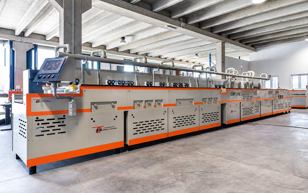
Horizontal PCB, flexible-circuit, glass, and panel lines move product continuously through spray, rinse, squeeze, and dry zones. Air knives are common in these conveyor-based systems because they can cover a working width without contact. SCHMID, for example, describes continuous DES equipment with transport for rigid, flexible, and ultra-flexible circuits and a dry-jet system at the line exit.
Semiconductor wafer wet benches often use batch cassettes, robotic transfers, spin rinse dryers, filtered nitrogen, or Marangoni drying. An air knife may serve equipment parts, carriers, selected substrates, or a qualified inline duty, but it should not be assumed to replace the approved wafer-drying method. State the product and process level clearly before integration begins.
A useful duty statement names the boundary, the liquid, the target, and the destination. For example: “Remove movable final-rinse water from both faces of a 600 mm PCB panel at 2 m/min and return the liquid to the final-rinse drain without visible droplets at inspection.” This is more useful than “dry the board.”
Interstage blow-off and final drying are different duties. Between tanks, the goal may be lower drag-in while keeping the surface wet. At the line exit, the goal may be a dry surface for inspection, coating, lamination, or packaging. An aggressive setting that is suitable at the end of the line can concentrate chemistry or create stains if used between process stages.
The dossier should include product size and mass, speed range, pitch, incoming liquid, chemistry, allowed return point, roller drawing, exhaust, utilities, enclosure space, material restrictions, controls, and acceptance tests. Add the smallest, largest, thinnest, and most flexible products.
Record upstream variability. Nozzles wear, rinse flow changes, rollers age, and hole patterns vary. The knife needs an operating window for approved variation, but it should not hide an uncontrolled rinse or failed mechanical dewatering stage.
The available treatment time is set by drying-zone length and conveyor speed. Product pitch also matters because closely spaced panels may shield edges or reduce the time available for the airflow to clear between pieces. A large blower does not solve a zone that is too short for the required water path.
Calculate normal and maximum throughput. Check product gaps and a board stopped under the knife. Variable-speed control can support recipes, but each approved point must remain on the blower curve after duct, filter, valve, and manifold losses.
Airflow should push liquid toward an approved drain or source tank, not toward the next chemical module. Leave gravity-drain distance where space allows. Use a drip break, partition, or recovery shield to stop liquid from bridging the boundary. The enclosure must prevent blown droplets from landing on a downstream roller and returning to the product.
For double-sided products, upper and lower knives may be opposed or staggered. A staggered layout often gives each face a clear discharge path. Lower knives need open access through roller gaps or a mesh support. Edges, holes, and carrier contact points may require a second angle or a small-hole knife, but every extra jet increases air demand and mist load.
The conveyor defines the air-knife distance. Roller runout, bearing wear, panel bow, web tension, product thickness, and mounting tolerance all change that distance in production. A bracket that is rigid on a drawing can move when ducts pull, guards vibrate, or technicians open the chamber.
Use stiff supports, repeatable adjustments, collision clearance, and position references. Thin products need short unsupported spans and balanced forces. Do not mask a transport fault by reducing air until drying becomes marginal; fix the roller, belt, guide, or support.
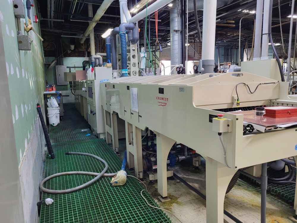
Wet benches already have extraction for chemical vapor and operator safety. The air knife adds momentum and can change chamber pressure. Excess extraction may bend the air sheet or draw mist across the product. Weak extraction may allow aerosol to escape into adjacent modules.
Test the knife with the enclosure closed and the exhaust at its normal production setting. Use transparent safe-access panels or temporary visualization methods during commissioning. Sloped trays, splash panels, and drains should stay effective during maximum rinse load and a line stop. Keep blower intake away from chemical exhaust, heated vapor, and entrained droplets.
A dedicated blower is often practical for continuous, wide-area coverage. Compressed air may fit localized or intermittent jets but needs a cleanliness and energy review. The final choice depends on total outlet area, duty cycle, required pressure, allowable noise, air quality, and the number of knives sharing the supply.
Body and support materials must match splash, vapor, temperature, and cleaning method. Aluminum may suit a separated final-rinse or dry zone. PVC, stainless steel, or titanium may be considered near stronger chemistry after a compatibility review. Include shims, fasteners, seals, ducts, filters, brackets, and drain hardware in the review.
With no product present, the jet may hit a wet roller or opposite knife and generate mist. The control system can reduce speed, close a valve, or keep the state unchanged if testing shows that cycling causes more problems. Choose deliberately.
A stopped product can receive prolonged air impact or heat. Interlocks should coordinate conveyor status, blower speed, valves, exhaust, upstream sprays, and alarm handling. The safe response depends on whether the priority is product protection, chemical containment, or maintaining a wet surface.
Start-up moisture, cold equipment, and cleaned guards can change the first pieces. Define purge, drain, warm-up, and verification. Link speed, knife position, airflow, exhaust, and product type in the recipe.
Provide access to clean the slot, inspect lips, change filters, drain condensate, check duct clamps, and service rollers. A knife hidden behind fixed guards will not receive reliable preventive maintenance. Quick removal is useful only when locating features or hard stops return it to the qualified angle and distance.
Track pressure drop, blower current or speed, slot condition, bracket position, exhaust state, and drying defects. A wet lane fixed across product width can indicate outlet contamination or inlet imbalance. Random re-wetting points to splash, drains, rollers, or enclosure airflow. Maintenance release should include a dry-pattern check at normal production conditions.
QXY Machinery lists 0.5-2 mm as a general blower-driven slot range and 0.5-1.5 mm for PCB surface drying. General references include 2-6 psi (0.14-0.42 bar) at the knife inlet, 20-50 mm working distance, and a 15-45 degree angle. Standard lengths include 150, 300, 450, 600, 800, and 1,000 mm, with custom lengths available. Dual inlets are commonly evaluated above 600 mm.
These are starting points, not final wet-bench settings. QXY also offers small-hole PCB knives with dual rows of 1 mm holes and air-to-air configurations for two-sided products. Final selection must use the actual working width, liquid load, product stability, duct loss, chemistry, exhaust behavior, line speed, and acceptance target.
Begin with transport and exhaust, then add airflow at low output. Run the full product range and normal incoming water load. Check top, bottom, edges, holes, roller contact bands, and a downstream observation point. Confirm where every removed drop goes.
Challenge maximum speed, liquid load, gaps, stops, restarts, filter loading, accepted roller wear, and recipe changes. Record pressure under flow, blower speed, slot, distance, angle, exhaust, conveyor speed, rinse condition, product, and result. Include dryness plus any required residue, ionic, particle, appearance, or downstream tests.
Air knife integration in continuous wet bench systems is complete only when the module holds its result through normal production states and maintenance. The best installation does not merely dry a sample. It fits the line clock, keeps liquid inside the approved wet zone, protects product handling, communicates with the controls, and can be restored after service.
QXY Machinery (Shenzhen Qixingyuan Machinery Equipment Co., Ltd.) is based in Shenzhen, China, and integrates R&D, design, production, and sales. The company has more than 10 years of focused experience in air knife systems for industrial drying, cleaning, and water blow-off.
For continuous wet processing lines, QXY Machinery can provide aluminum, stainless steel, PVC, titanium, small-hole PCB, and air-to-air knife configurations, together with blowers, ducts, supports, splash control, collection trays, conveyors, and electrical controls. Custom review can cover wet-bench drawings, product range, chemistry, working width, speed, liquid return, exhaust, utilities, control signals, and acceptance tests.
Q: Where should an air knife be installed in a continuous wet bench?
A: Install it where displaced liquid has an approved return or drain path. Common positions include interstage drag-out control, after final rinse, and before inspection or another moisture-sensitive process.
Q: Can one air knife setting serve every product recipe?
A: Usually not. Product width, thickness, flexibility, hole pattern, line speed, and incoming liquid load can require different blower speed, knife position, or conveyor settings.
Q: Should air knives run when no product is present?
A: That depends on mist, energy, cycling, and control response. Test the empty-gap condition and choose a defined state such as reduced speed, valve closure, or continuous operation.
Q: How should an air knife respond to a line stop?
A: The controls should coordinate transport, airflow, sprays, exhaust, and alarms. The response must prevent prolonged product impact, uncontrolled drying, mist release, or chemical carryover.
Q: Is a blower or compressed air better for a continuous wet bench?
A: A blower often suits wide, continuous coverage, while compressed air can fit localized or intermittent duties. Compare outlet area, duty cycle, cleanliness, energy, pressure, noise, and control needs.
Q: What data is needed for air knife integration in continuous wet bench systems?
A: Provide the process sequence, product range, line speed, pitch, liquid and chemistry, allowed return point, transport and exhaust drawings, utilities, controls, materials restrictions, and acceptance tests.
Need a custom air knife solution? Send us your application details, material requirement ,or air source type . Our engineering team will help you select the right model.

Shenzhen Qixingyuan Machinery Equipment Co., Ltd.
info@airknifecn.com
Building 8, Wanfeng Third Industrial Zone, Xinqiao Street, Bao'an District, Shenzhen, Guangdong, China


