

A machined housing can look dry on its upper face and still release coolant when it turns over at assembly. The liquid was hidden in a tapped hole, a groove, or a pocket beneath the fixture. More airflow across the visible face may leave that trapped liquid almost untouched.
An Air Knife for machined parts uses a directed sheet of air to displace accessible liquid. Its suitability depends on whether the airflow reaches the wet feature and whether the coolant has a route out. Threads and recesses need more attention than an uninterrupted flat surface.
For manufacturing engineers and maintenance teams, the useful starting point is a drawing of the part in its actual handling position. Mark where coolant remains, where air can enter, and where the liquid can leave. Use that map to decide whether broad blow-off, controlled repositioning, or localized treatment deserves a trial.
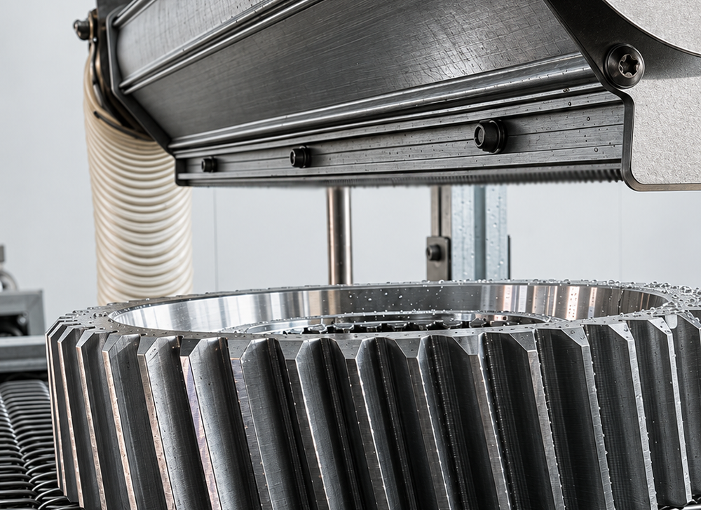
Removing free coolant is different from removing an oily film, fine particles, or chemical residue. An air knife may displace liquid without making a surface suitable for bonding, coating, precision assembly, or a specified cleanliness test. Agree on the next operation's requirements before selecting the equipment.
Identify the actual fluid: a water-mixed metalworking fluid, a neat cutting oil, or rinse water after a cleaning process. Record its condition and the time between machining and blow-off. A trial using clean water alone should not be accepted as proof of performance with production coolant.
Decide which features must pass inspection. A requirement for no dripping during transfer differs from a requirement for a clean internal thread before an adhesive is applied. If washing or degreasing is required, retain that operation and evaluate air knife drying at the appropriate point afterward.
External threads expose more surface to an air stream when the part can be presented from several directions. For a proposed trial, consider a supported rotation or a second viewing direction rather than judging the full circumference from the side facing one outlet. Check the thread roots and the shoulder where liquid can remain.
Internal threads present a different access problem. A straight-through threaded hole and a blind tapped hole should not share an acceptance assumption. In the through hole, first check whether the fixture leaves the opposite opening clear. In a blind hole, liquid and incoming air must use the same mouth, so blowing across the opening does not establish that its bottom is clear.
Treat deep internal threads as a separate trial feature. If an air knife misses them, assess controlled orientation changes or a purpose-designed local nozzle arrangement with the equipment supplier. Don't improvise a sealed lance into a blind hole or assume a stronger blast will solve inaccessible geometry.
For coolant removal from grooves, sketch the groove path rather than only its width. An open channel leading to an edge offers a different drainage opportunity from a closed annular groove. Ask where displaced liquid will go at the end of the air exposure.
As a trial variable, direct the airflow toward an available exit and inspect both ends of the groove afterward. For a circumferential feature, evaluate whether controlled rotation exposes the sheltered side. These are candidate arrangements, not universal angle recommendations.
Include nearby shoulders, steps, and clamps in the sketch. A clamp can block the air or obstruct the outlet path even when the groove itself appears accessible. Changing the fixture contact position may be more useful than increasing the supply setting.
An upward-facing pocket should not be treated as a flat plate. Before blowing into it, assess whether the part can be safely tilted so free liquid drains toward a low edge. Preserve the support and contact limits of the machined surfaces.
A pocket with ribs or undercuts needs inspection behind those obstructions. If the air passes over the mouth, the result at the visible rim tells little about the sheltered floor. Consider a second part orientation or localized delivery, then inspect the specific area that previously retained coolant.
For a hypothetical housing with an open pocket and blind mounting holes, use separate checks for the pocket floor and each hole family. Passing the easy pocket does not qualify the blind holes. This feature-based approach also helps identify when air blow-off alone is unsuitable.
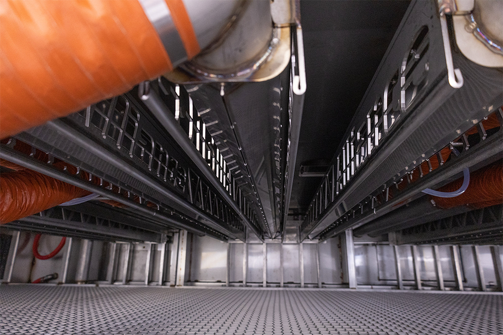
A broad air sheet suits a coverage task; a local nozzle concentrates treatment at a selected feature. Some applications may justify both, but adding outlets without resolving access can increase air demand while leaving the same trapped liquid.
Specify the part's orientation and support before choosing knife length. Cover the surfaces that actually pass through the treatment zone, including permitted position variation. Where fixtures carry several parts, inspect the parts behind the leading row and the areas close to the supports.
Fragile edges, precision faces, and small parts may rule out uncontrolled tumbling. A fixture or indexed presentation can make the exposure repeatable, provided it does not conceal the target features. Confirm that proposed rotation or tilting is compatible with the handling system.
Distinguish blower-fed air knives from compressed-air devices when requesting a proposal. Their supply arrangements and operating requirements differ. Ask the supplier to specify the installed duty with all outlets operating, including connecting pipework. Neither a motor rating nor a nominal supply pressure alone establishes coolant-removal performance.
Keep air quality in the review. Identify what the next operation permits on the surface and specify the necessary control of particles, moisture, and oil in the delivered air. A suitable air source must be assessed with its intake, filtration, distribution, and maintenance arrangements.
Select representative parts with the deepest relevant recess, the least accessible thread, and the most difficult fixture position. Include the real coolant and normal incoming liquid load. Record the initial drain time so an unusually long wait does not make the proposed station appear more capable than it is.
Start with the approved operating range for the equipment. Keep a record of knife position, outlet direction, working distance, part orientation, exposure time, and supply setting. Change one factor at a time where practical. If a geometry change clears the retained liquid, document that relationship before adjusting other settings.
For moving parts, exposure depends on the distance travelled through the effective treatment region and the travel speed. For an indexed fixture, use the actual treatment dwell. Include loading, repositioning, and unloading when comparing the complete cycle with the production requirement.
Inspect after the part has stopped safely. Good lighting and a suitable inspection aid may reveal liquid in accessible features; a borescope may help where direct viewing is blocked. Use a documented method that the quality team accepts. A photograph of the outside is not evidence of an acceptable internal surface.
Then put the part through its next normal orientation change. A controlled tilt over a clean collection surface can reveal retained liquid that was missed at the outlet. Define the observation interval and inspection locations in advance so different operators judge the same condition.
If the requirement concerns residue or particulate cleanliness, use the relevant approved test in addition to visual inspection. For quantitative liquid-removal comparisons, any weighing method needs controlled incoming conditions and sufficient measurement resolution; ordinary part-to-part mass variation can obscure the result.
Repeat the successful arrangement at the required throughput and after a normal changeover. Retain the settings against the part and fixture revision. Approve an air knife for machined parts only for the tested operating range, and record unresolved wet features instead of reporting a blanket drying result.
Blowing metalworking fluid can generate airborne mist and eject loose chips. Review the station's enclosure, extraction, drainage, and operator access with the site's responsible personnel. A splash guard alone does not demonstrate adequate mist control.
Prefer a contained, assessed process over open manual blow-down. Establish how the station stops, how access is controlled, and when it is appropriate to open the enclosure after treatment. Check extraction performance under the proposed air-delivery conditions.
Collect displaced liquid away from downstream parts and walking surfaces. Keep collected coolant separate from any decision to return it to the machining system; contamination and fluid-management requirements need review first. Remove accumulated swarf using the approved method, with the equipment safely isolated for maintenance.
QXY Machinery offers industrial air knives and integrated air knife drying systems. Its published system range includes configurable air delivery, conveyors, adjustable supports, splash protection, and liquid collection.
For a machined-parts project, send the drawing and coolant-removal requirements for an application review. Ask QXY to assess the treatment layout and trial needs for the specific threads, grooves, and recesses. A general equipment configuration is not evidence that a particular part has passed its acceptance test.
Can an air knife for machined parts run inside an existing CNC enclosure?
Possibly, subject to review by the machine and air-system suppliers. Check mounting clearance, machine movement, extraction capacity, coolant compatibility, controls, and service access. Existing enclosure space does not by itself establish that the installation is suitable.
Should coolant be removed before or after parts are unclamped?
Choose according to access and handling requirements. Clamping may stabilize the part but hide wet features. Unclamping may improve access while adding handling risk. Trial the proposed sequence and inspect the surfaces previously covered by the fixture.
Can one setting cover different thread sizes?
Only after the relevant range is checked. Hole depth, opening size, orientation, fixture clearance, and coolant condition can differ alongside thread size. Group parts by the conditions that affect access and drainage, then retain approved settings for each group.
What should be checked if the station gradually leaves more coolant behind?
Compare the current setup with the approved record. Check part presentation, incoming fluid load, outlet condition, air-supply performance, drainage, and maintenance status. Investigate changes before increasing the setting, and confirm the result with the same feature inspection used at acceptance.
Need a custom air knife solution? Send us your application details, material requirement ,or air source type . Our engineering team will help you select the right model.

Shenzhen Qixingyuan Machinery Equipment Co., Ltd.
info@airknifecn.com
Building 8, Wanfeng Third Industrial Zone, Xinqiao Street, Bao'an District, Shenzhen, Guangdong, China


