

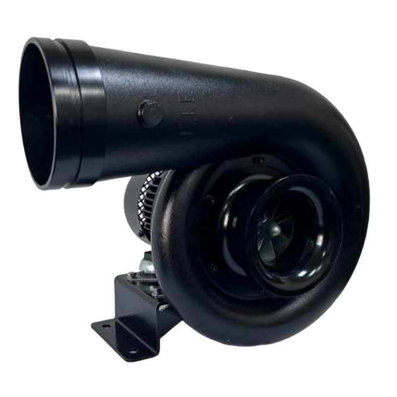
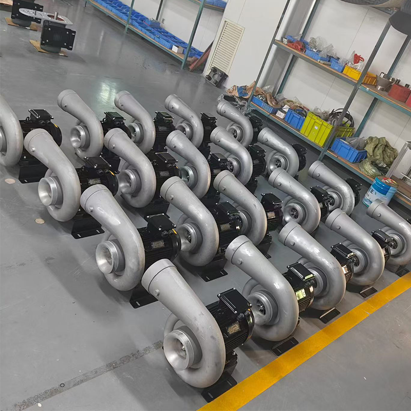
High-Speed Centrifugal Air Delivery
Permanent-Magnet Synchronous Motor Platform
Speed-Based Process Adjustment
Ternary-Flow Impeller
This four-model range is organized around two airflow classes and two pressure classes. Customers can use the matrix for initial screening, then verify the final choice against the relevant performance curve and the pressure loss of the complete air-delivery system.
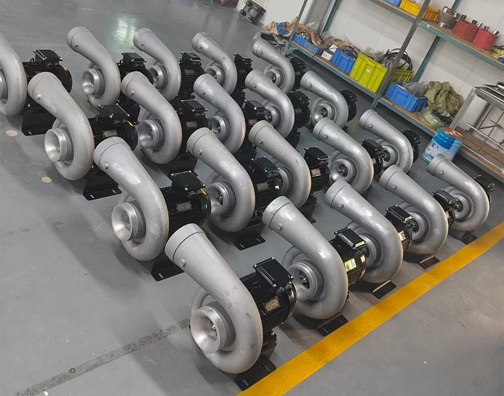
The table below positions each nominal power class for a first-pass selection. The values are reproduced from the supplied specification sheets. They are not a substitute for confirming one complete operating point on the corresponding curve.
| Power class | Model identifier | Rated airflow | Rated pressure | Rated speed | Current | Initial selection position |
| 4kW | SMD/FD-5.5-4B | 1,200 m³/h | 11 kPa | 19,000 rpm | 8 A | Moderate airflow / moderate pressure |
| 5.5 kW | SMD/FD-7.5-4A | 1,200 m³/h | 15 kPa | 21,000 rpm | 11 A | Moderate airflow / higher pressure |
| 7.5 kW | SMD/FD-7.5-6B | 1,800 m³/h | 11 kPa | 19,000 rpm | 12.1 A | Higher airflow / moderate pressure |
| 11 kW | SMD/FD-11-6A | 1,800 m³/h | 15 kPa | 22,000 rpm | 17.6 A | Higher airflow / higher pressure |
| Target airflow class | Target pressure class | Evaluate first | Model identifier | Decision cue |
About 1,200 m³/h | About 11 kPa | 4 kW | SMD/FD-5.5-4B | Lower-flow / moderate-pressure starting point |
About 1,200 m³/h | About 15 kPa | 5.5 kW | SMD/FD-7.5-4A | Lower-flow / higher-pressure starting point |
About 1,800 m³/h | About 11 kPa | 7.5 kW | SMD/FD-7.5-6B | Higher-flow / moderate-pressure starting point |
About 1,800 m³/h | About 15 kPa | 11 kW | SMD/FD-11-6A | Higher-flow / higher-pressure starting point |
The same airflow number can produce very different results when product width, slot geometry, duct resistance, or line speed changes. Use the application matrix to define what the blower must accomplish before selecting a power class.
| Function | Process objective | Selection inputs |
| Water blow-off and drying | Remove droplets or surface films after washing, rinsing, coating, or machining | Product width and shape; water load; line speed; number and length of air knives; slot width; stand-off distance |
| Surface cleaning | Dislodge dust, chips, fibers, or loose particles | Particle size and adhesion; cleaning width; recesses; collection method; material compatibility |
| Cooling | Accelerate convective heat removal from a product or component | Heat load; inlet-air temperature; product geometry; exposure time; permitted final temperature |
| Air curtain or separation | Create a controlled sheet of air across an opening or process zone | Opening width; cross-drafts; required air velocity; containment objective; continuous duty |
| Multiple air knives | Supply two or more blow-off zones from one blower | Combined flow; branch balance; manifold losses; simultaneous operation; valve positions |
| Variable production | Adjust output for changing products, speeds, or moisture loads | Required operating range; control signal; minimum continuous speed; process feedback; drive limits |
More total outlet area generally increases airflow demand. Wider products, more air knives, and higher line speeds commonly move the selection toward the higher-flow class.
More restriction increases pressure demand. Narrow passages, restrictive nozzles, loaded filters, long ducts, undersized piping, and numerous bends can move the selection toward the higher-pressure class.
More variation requires control margin. A process with changing product widths, loads, or conveyor speeds benefits from a duty point that can be adjusted without leaving the approved curve and electrical limits.
The range uses a high-speed centrifugal layout to provide the airflow and outlet pressure required by industrial air-knife systems. Four nominal power classes make it possible to select for airflow and resistance instead of choosing only by motor size.
The supplied sheets identify a rare-earth permanent-magnet three-phase synchronous motor, IP54 motor protection, and Class F insulation. The source also lists high-temperature-resistant magnetic material and a low-temperature-rise design as anti-demagnetization measures.
Each chart presents multiple rotational-speed curves. With the approved high-frequency drive, speed can be set to match changing process loads while the operating point remains inside the documented performance and electrical envelope.
All four sheets identify a ternary-flow impeller structure. This feature describes the impeller geometry; it does not replace curve-based verification of the required airflow and pressure.
| Parameter | Source-listed value | Selection or publishing note |
| Working temperature | 20°C–60°C | Confirm whether this is inlet-air temperature, ambient temperature, or both. |
| Atmospheric condition | 101 kPa | Confirm curve reference conditions and whether pressure is absolute. |
| Bare-machine noise | ≤85 dB | Installed noise depends on speed, duty point, mounting, ducting, silencers, room acoustics, and test method. |
| Motor protection | IP54 | Shown under the motor section; do not apply it to the complete assembly without confirmation. |
| Insulation class | Class F | Use with the approved drive settings and site thermal conditions. |
| Rated voltage | 380 V AC | Confirm facility supply, phase, tolerance, and the matched controller package. |
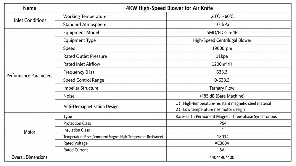
| Parameter | Source-declared value |
| Nominal power class | 4 kW |
| Model identifier | SMD/FD-5.5-4B |
| Equipment type | High-speed centrifugal blower |
| Rated speed | 19,000 rpm |
| Rated inlet airflow | 1,200 m³/h |
| Rated outlet pressure | 11 kPa |
| Maximum listed frequency | 633.3 Hz |
| Listed control range | 0–633.3 (source-listed; unit not printed) |
| Rated voltage / current | 380 V AC / 8 A |
The supplied chart shows solid pressure curves at 15,000, 17,000, and 19,000 rpm. At a fixed speed, the solid pressure curve falls as airflow rises. Use the 19,000 rpm line for the highest plotted capability, then consider a lower speed when the process requires less airflow or pressure.
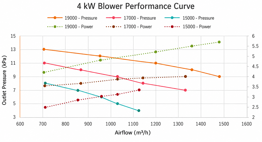
Operating point: the required airflow and the calculated system pressure must be satisfied at the same point on one plotted speed line.
Speed margin: select a controllable operating region rather than relying on an unplotted point or extrapolating beyond the curve.
Electrical limit: the dotted series is identified as power in the source, but its right-hand axis has no title or unit; confirm the scale before using it for approval.
| Parameter | Source-declared value |
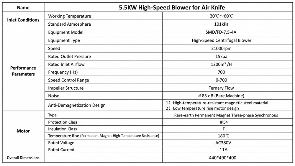
| Nominal power class | 5.5 kW |
| Model identifier | SMD/FD-7.5-4A |
| Equipment type | High-speed centrifugal blower |
| Rated speed | 21,000 rpm |
| Rated inlet airflow | 1,200 m³/h |
| Rated outlet pressure | 15 kPa |
| Maximum listed frequency | 700 Hz |
| Listed control range | 0–700 (source-listed; unit not printed) |
| Rated voltage / current | 380 V AC / 11 A |
The supplied chart shows solid pressure curves at 15,000, 17,000, 19,000, and 21,000 rpm. The 21,000 rpm pressure line provides the highest plotted capability in this group. Confirm the selected duty point and the associated electrical loading with the approved motor-and-drive package.
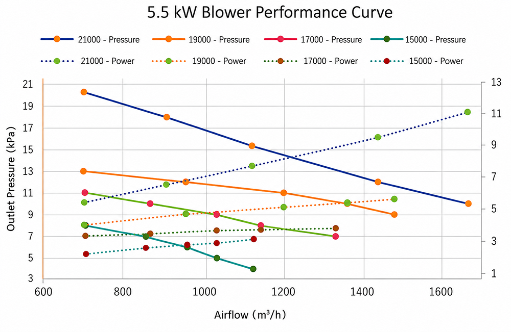
Operating point: the required airflow and the calculated system pressure must be satisfied at the same point on one plotted speed line.
Speed margin: select a controllable operating region rather than relying on an unplotted point or extrapolating beyond the curve.
Electrical limit: the dotted series is identified as power in the source, but its right-hand axis has no title or unit; confirm the scale before using it for approval.
| Parameter | Source-declared value |
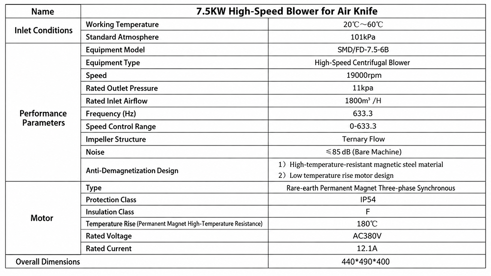
| Nominal power class | 7.5 kW |
| Model identifier | SMD/FD-7.5-6B |
| Equipment type | High-speed centrifugal blower |
| Rated speed | 19,000 rpm |
| Rated inlet airflow | 1,800 m³/h |
| Rated outlet pressure | 11 kPa |
| Maximum listed frequency | 633.3 Hz |
| Listed control range | 0–633.3 (source-listed; unit not printed) |
| Rated voltage / current | 380 V AC / 12.1 A |
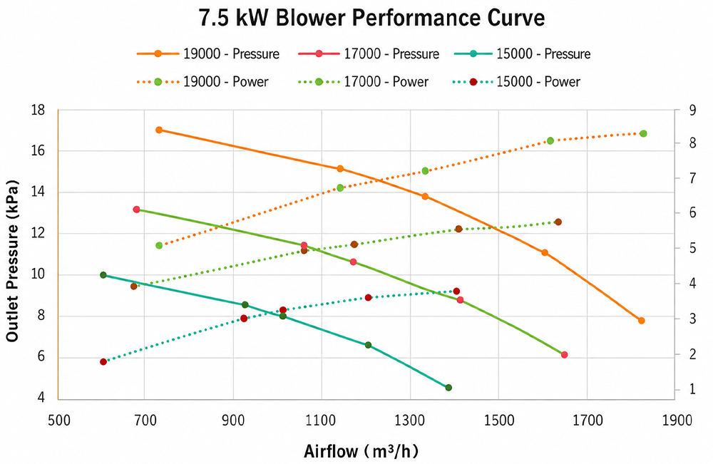
The supplied chart shows solid pressure curves at 15,000, 17,000, and 19,000 rpm. Use the curve—not the headline airflow alone—to establish how much pressure is available at the total flow demanded by the complete air-knife network. The source-listed rated pair requires engineering confirmation against the chart.
Operating point: the required airflow and the calculated system pressure must be satisfied at the same point on one plotted speed line.
Speed margin: select a controllable operating region rather than relying on an unplotted point or extrapolating beyond the curve.
Electrical limit: the dotted series is identified as power in the source, but its right-hand axis has no title or unit; confirm the scale before using it for approval.
| Parameter | Source-declared value |
| Nominal power class | 11 kW |
| Model identifier | SMD/FD-11-6A |
| Equipment type | High-speed centrifugal blower |
| Rated speed | 22,000 rpm |
| Rated inlet airflow | 1,800 m³/h |
| Rated outlet pressure | 15 kPa |
| Maximum listed frequency | 733.3 Hz |
| Listed control range | 0–733.3 (source-listed; unit not printed) |
| Rated voltage / current | 380 V AC / 17.6 A |
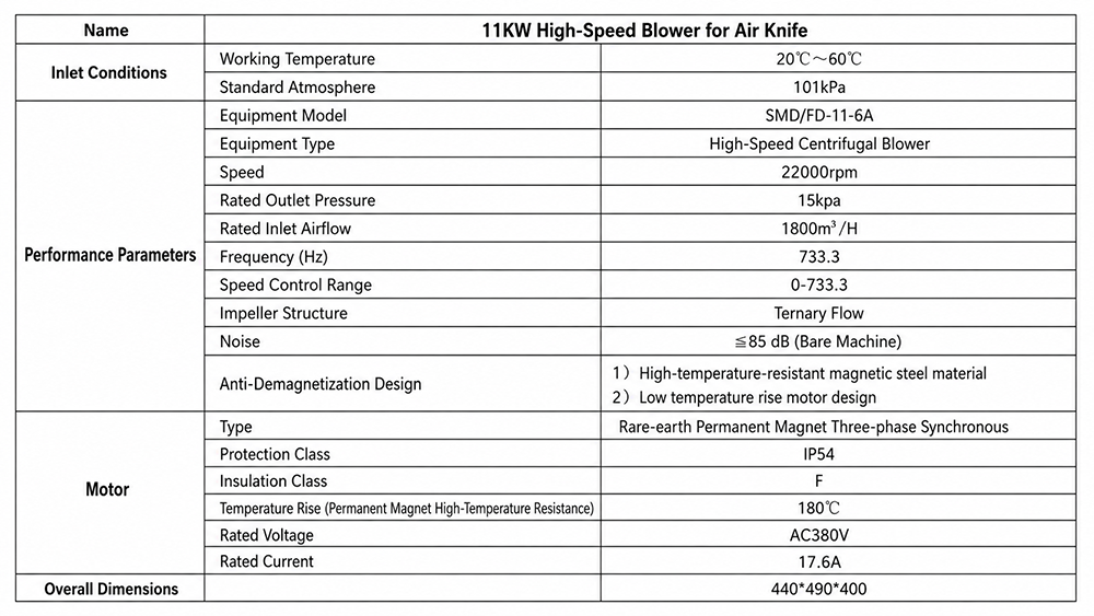
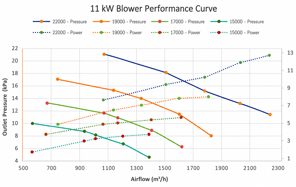
The supplied chart shows solid pressure curves at 15,000, 17,000, 19,000, and 22,000 rpm. Use the 22,000 rpm line for the highest plotted capability. A lower-speed line may provide the required duty with additional control margin when the process does not need maximum output.
Operating point: the required airflow and the calculated system pressure must be satisfied at the same point on one plotted speed line.
Speed margin: select a controllable operating region rather than relying on an unplotted point or extrapolating beyond the curve.
Electrical limit: the dotted series is identified as power in the source, but its right-hand axis has no title or unit; confirm the scale before using it for approval.
A blower does not deliver one fixed airflow and one fixed pressure independently. The actual operating point is created where the blower curve intersects the resistance of the complete system. Follow this sequence for every quotation and installation.
Calculate the total airflow required by every air knife and open outlet operating at the same time.
Calculate pressure loss through the air knives, filter, silencer, manifolds, valves, reducers, flexible connectors, ductwork, and bends.
Mark the required airflow on the horizontal axis and the required outlet pressure on the left vertical axis.
Identify the plotted speed line that reaches the required point without extrapolation.
Check available control margin for process variation, filter loading, and future line-speed changes.
Confirm the secondary dotted trace, its unit, and the approved electrical limit with the supplier before authorizing continuous operation.
Correct for actual inlet temperature, altitude, atmospheric pressure, and any other condition that differs from the curve reference condition.
Validate the commissioned duty point by measuring speed, airflow or pressure, current, temperature, noise, and vibration under real operating conditions.
Air-knife length, slot width, inlet size, internal profile, and stand-off distance all affect flow demand, resistance, impact velocity, and coverage. Provide drawings or dimensions for every air knife that will operate simultaneously.
Size ducts and manifolds for the required total flow while limiting avoidable pressure loss. Minimize abrupt transitions, undersized fittings, and unnecessary bends. Support the ductwork independently so external loads are not transferred to the blower casing.
An inlet filter protects the blower and process, but a dirty or restrictive element moves the operating point by increasing resistance. Inlet or discharge silencers also add loss. Include both clean and service-limit pressure drop in the selection.
For two or more branches, calculate combined demand and the resistance of each path. Use a balanced manifold or appropriate balancing devices so one branch does not receive most of the available flow.
Manual speed setting is suitable for a stable process. Variable lines may use a remote setpoint or pressure, airflow, product-presence, or line-speed feedback. The control method must remain within the supplier-approved speed, current, cooling, and ramp limits.
Confirm material compatibility and suitability before handling corrosive gas, combustible dust, hazardous atmospheres, high humidity, oil mist, aggressive chemicals, or inlet temperatures outside the stated working range. No suitability claim for these conditions should be inferred from the general specifications.
The listed operating frequencies—633.3, 700, or 733.3 Hz depending on the model—are consistent with high-speed motor-drive output, not ordinary facility supply frequency. Treat the blower, motor, drive, cable, and protection settings as one approved system.
Do not connect the motor directly to a standard 50 or 60 Hz supply based only on the 380 V AC label.
Confirm whether the controller is included and obtain approved motor data, output frequency, current limit, ramp time, deceleration method, and minimum continuous speed.
Verify facility voltage, phase, frequency, available capacity, grounding, cable requirements, electrical protection, and electromagnetic-compatibility measures.
Integrate emergency stop, process interlocks, overload protection, alarms, and permissive signals according to the site safety design.
Install the blower on a rigid, level support with mounting and vibration-control components suitable for the machine and site.
Keep the inlet unobstructed and provide clean inlet air. Establish a filter inspection and replacement schedule for the actual environment.
Maintain service access and adequate cooling around the blower and drive. Any acoustic enclosure must preserve ventilation.
Do not operate continuously against a closed or excessively restricted discharge. Keep the duty point inside the approved curve.
Send the following information with the quotation request. Complete data allows the blower, controller, air knife, and duct system to be checked as one operating package.
| Information group | Details to provide |
| Process | Drying, water blow-off, cleaning, cooling, air curtain, or other duty; product material and shape; required result |
| Production | Conveyor or line speed; batch or continuous operation; daily operating hours; product variation |
| Air knives | Quantity; length; slot width; inlet size; orientation; stand-off distance; simultaneous operation |
| Duty point | Required total airflow and outlet pressure, if known; acceptable adjustment range |
| Air path | Duct diameter and length; bends; reducers; valves; flexible connectors; filters; silencers; manifold layout |
Shenzhen Qixingyuan Machinery Equipment Co., Ltd.
We are a specialized manufacturer of industrial air knives and complete air-delivery solutions. Our product range includes aluminum alloy, stainless steel, and PVC air knives, together with mounting hardware and system accessories. CNC precision machining and in-process inspection help maintain consistent dimensions and quality before shipment.
Our OEM and ODM services support customers in electronics, automotive, food and beverage, pharmaceutical, and general manufacturing applications. Customers may provide drawings, samples, equipment dimensions, or application details, and our engineering team will develop an air-knife solution that fits the machine and process requirements.
We support high-speed centrifugal blower selection and air-knife system matching according to the required airflow, outlet pressure, air-knife configuration, and operating conditions.
For this high-speed blower series, please provide:
Application and required drying, blow-off, cleaning, or cooling result
Number of air knives operating simultaneously
Air-knife length, slot width, and inlet connection size
Required total airflow and outlet pressure, if known
Duct diameter, total length, bends, reducers, filters, and silencers
Ambient and inlet-air temperature
Site altitude or atmospheric pressure
Available power supply, voltage, phase, and frequency
Required speed-control or automation method
Continuous or intermittent operating schedule
Installation space and preferred connection orientation
Workplace noise requirement
Required quantity
Existing blower model, equipment drawing, or system reference number
These details allow us to check the operating point against the relevant performance curve and prepare a more accurate blower and air-knife system quotation.
Start with the required airflow and outlet pressure. The supplied rated values position the 4 kW model at 1,200 m³/h and 11 kPa, the 5.5 kW model at 1,200 m³/h and 15 kPa, the 7.5 kW model at 1,800 m³/h and 11 kPa, and the 11 kW model at 1,800 m³/h and 15 kPa. Treat this as initial screening; finalize the choice only after checking one simultaneous duty point on the relevant performance curve.
No. Filters, silencers, ducts, manifolds, fittings, and the air-knife slot create resistance. The blower must deliver the required airflow at the calculated system pressure. A high free-flow number does not prove that the same airflow is available after the air-delivery system is connected.
Do not assume direct connection is permitted. The motors are listed with operating frequencies up to 633.3, 700, or 733.3 Hz and require a compatible high-frequency drive with supplier-approved parameters. Confirm the complete motor-and-controller package before installation.
Yes, when the combined airflow demand and total pressure loss fall within the selected curve and the manifold distributes air evenly. Variable speed can accommodate changing products, but the minimum continuous speed, cooling needs, current limit, and permitted control range must be confirmed.
Installed airflow changes with filter condition, duct resistance, speed setting, inlet temperature, altitude, and air-knife geometry. Installed noise is also affected by mounting, duct resonance, silencers, enclosures, room acoustics, operating point, and measurement method. Record actual readings during commissioning.
Provide the required airflow, pressure, air-knife dimensions, line speed, duct layout, site conditions, and electrical supply. The selection can then be checked against the appropriate 4 kW, 5.5 kW, 7.5 kW, or 11 kW curve.
This four-model range is organized around two airflow classes and two pressure classes. Customers can use the matrix for initial screening, then verify the final choice against the relevant performance curve and the pressure loss of the complete air-delivery system.
The table below positions each nominal power class for a first-pass selection. The values are reproduced from the supplied specification sheets. They are not a substitute for confirming one complete operating point on the corresponding curve.
| Power class | Model identifier | Rated airflow | Rated pressure | Rated speed | Current | Initial selection position |
| 4kW | SMD/FD-5.5-4B | 1,200 m³/h | 11 kPa | 19,000 rpm | 8 A | Moderate airflow / moderate pressure |
| 5.5 kW | SMD/FD-7.5-4A | 1,200 m³/h | 15 kPa | 21,000 rpm | 11 A | Moderate airflow / higher pressure |
| 7.5 kW | SMD/FD-7.5-6B | 1,800 m³/h | 11 kPa | 19,000 rpm | 12.1 A | Higher airflow / moderate pressure |
| 11 kW | SMD/FD-11-6A | 1,800 m³/h | 15 kPa | 22,000 rpm | 17.6 A | Higher airflow / higher pressure |
| Target airflow class | Target pressure class | Evaluate first | Model identifier | Decision cue |
About 1,200 m³/h | About 11 kPa | 4 kW | SMD/FD-5.5-4B | Lower-flow / moderate-pressure starting point |
About 1,200 m³/h | About 15 kPa | 5.5 kW | SMD/FD-7.5-4A | Lower-flow / higher-pressure starting point |
About 1,800 m³/h | About 11 kPa | 7.5 kW | SMD/FD-7.5-6B | Higher-flow / moderate-pressure starting point |
About 1,800 m³/h | About 15 kPa | 11 kW | SMD/FD-11-6A | Higher-flow / higher-pressure starting point |
The same airflow number can produce very different results when product width, slot geometry, duct resistance, or line speed changes. Use the application matrix to define what the blower must accomplish before selecting a power class.
| Function | Process objective | Selection inputs |
| Water blow-off and drying | Remove droplets or surface films after washing, rinsing, coating, or machining | Product width and shape; water load; line speed; number and length of air knives; slot width; stand-off distance |
| Surface cleaning | Dislodge dust, chips, fibers, or loose particles | Particle size and adhesion; cleaning width; recesses; collection method; material compatibility |
| Cooling | Accelerate convective heat removal from a product or component | Heat load; inlet-air temperature; product geometry; exposure time; permitted final temperature |
| Air curtain or separation | Create a controlled sheet of air across an opening or process zone | Opening width; cross-drafts; required air velocity; containment objective; continuous duty |
| Multiple air knives | Supply two or more blow-off zones from one blower | Combined flow; branch balance; manifold losses; simultaneous operation; valve positions |
| Variable production | Adjust output for changing products, speeds, or moisture loads | Required operating range; control signal; minimum continuous speed; process feedback; drive limits |
More total outlet area generally increases airflow demand. Wider products, more air knives, and higher line speeds commonly move the selection toward the higher-flow class.
More restriction increases pressure demand. Narrow passages, restrictive nozzles, loaded filters, long ducts, undersized piping, and numerous bends can move the selection toward the higher-pressure class.
More variation requires control margin. A process with changing product widths, loads, or conveyor speeds benefits from a duty point that can be adjusted without leaving the approved curve and electrical limits.
The range uses a high-speed centrifugal layout to provide the airflow and outlet pressure required by industrial air-knife systems. Four nominal power classes make it possible to select for airflow and resistance instead of choosing only by motor size.
The supplied sheets identify a rare-earth permanent-magnet three-phase synchronous motor, IP54 motor protection, and Class F insulation. The source also lists high-temperature-resistant magnetic material and a low-temperature-rise design as anti-demagnetization measures.
Each chart presents multiple rotational-speed curves. With the approved high-frequency drive, speed can be set to match changing process loads while the operating point remains inside the documented performance and electrical envelope.
All four sheets identify a ternary-flow impeller structure. This feature describes the impeller geometry; it does not replace curve-based verification of the required airflow and pressure.
| Parameter | Source-listed value | Selection or publishing note |
| Working temperature | 20°C–60°C | Confirm whether this is inlet-air temperature, ambient temperature, or both. |
| Atmospheric condition | 101 kPa | Confirm curve reference conditions and whether pressure is absolute. |
| Bare-machine noise | ≤85 dB | Installed noise depends on speed, duty point, mounting, ducting, silencers, room acoustics, and test method. |
| Motor protection | IP54 | Shown under the motor section; do not apply it to the complete assembly without confirmation. |
| Insulation class | Class F | Use with the approved drive settings and site thermal conditions. |
| Rated voltage | 380 V AC | Confirm facility supply, phase, tolerance, and the matched controller package. |
| Parameter | Source-declared value |
| Nominal power class | 4 kW |
| Model identifier | SMD/FD-5.5-4B |
| Equipment type | High-speed centrifugal blower |
| Rated speed | 19,000 rpm |
| Rated inlet airflow | 1,200 m³/h |
| Rated outlet pressure | 11 kPa |
| Maximum listed frequency | 633.3 Hz |
| Listed control range | 0–633.3 (source-listed; unit not printed) |
| Rated voltage / current | 380 V AC / 8 A |
The supplied chart shows solid pressure curves at 15,000, 17,000, and 19,000 rpm. At a fixed speed, the solid pressure curve falls as airflow rises. Use the 19,000 rpm line for the highest plotted capability, then consider a lower speed when the process requires less airflow or pressure.
Operating point: the required airflow and the calculated system pressure must be satisfied at the same point on one plotted speed line.
Speed margin: select a controllable operating region rather than relying on an unplotted point or extrapolating beyond the curve.
Electrical limit: the dotted series is identified as power in the source, but its right-hand axis has no title or unit; confirm the scale before using it for approval.
| Parameter | Source-declared value |
| Nominal power class | 5.5 kW |
| Model identifier | SMD/FD-7.5-4A |
| Equipment type | High-speed centrifugal blower |
| Rated speed | 21,000 rpm |
| Rated inlet airflow | 1,200 m³/h |
| Rated outlet pressure | 15 kPa |
| Maximum listed frequency | 700 Hz |
| Listed control range | 0–700 (source-listed; unit not printed) |
| Rated voltage / current | 380 V AC / 11 A |
The supplied chart shows solid pressure curves at 15,000, 17,000, 19,000, and 21,000 rpm. The 21,000 rpm pressure line provides the highest plotted capability in this group. Confirm the selected duty point and the associated electrical loading with the approved motor-and-drive package.
Operating point: the required airflow and the calculated system pressure must be satisfied at the same point on one plotted speed line.
Speed margin: select a controllable operating region rather than relying on an unplotted point or extrapolating beyond the curve.
Electrical limit: the dotted series is identified as power in the source, but its right-hand axis has no title or unit; confirm the scale before using it for approval.
| Parameter | Source-declared value |
| Nominal power class | 7.5 kW |
| Model identifier | SMD/FD-7.5-6B |
| Equipment type | High-speed centrifugal blower |
| Rated speed | 19,000 rpm |
| Rated inlet airflow | 1,800 m³/h |
| Rated outlet pressure | 11 kPa |
| Maximum listed frequency | 633.3 Hz |
| Listed control range | 0–633.3 (source-listed; unit not printed) |
| Rated voltage / current | 380 V AC / 12.1 A |
The supplied chart shows solid pressure curves at 15,000, 17,000, and 19,000 rpm. Use the curve—not the headline airflow alone—to establish how much pressure is available at the total flow demanded by the complete air-knife network. The source-listed rated pair requires engineering confirmation against the chart.
Operating point: the required airflow and the calculated system pressure must be satisfied at the same point on one plotted speed line.
Speed margin: select a controllable operating region rather than relying on an unplotted point or extrapolating beyond the curve.
Electrical limit: the dotted series is identified as power in the source, but its right-hand axis has no title or unit; confirm the scale before using it for approval.
| Parameter | Source-declared value |
| Nominal power class | 11 kW |
| Model identifier | SMD/FD-11-6A |
| Equipment type | High-speed centrifugal blower |
| Rated speed | 22,000 rpm |
| Rated inlet airflow | 1,800 m³/h |
| Rated outlet pressure | 15 kPa |
| Maximum listed frequency | 733.3 Hz |
| Listed control range | 0–733.3 (source-listed; unit not printed) |
| Rated voltage / current | 380 V AC / 17.6 A |
The supplied chart shows solid pressure curves at 15,000, 17,000, 19,000, and 22,000 rpm. Use the 22,000 rpm line for the highest plotted capability. A lower-speed line may provide the required duty with additional control margin when the process does not need maximum output.
Operating point: the required airflow and the calculated system pressure must be satisfied at the same point on one plotted speed line.
Speed margin: select a controllable operating region rather than relying on an unplotted point or extrapolating beyond the curve.
Electrical limit: the dotted series is identified as power in the source, but its right-hand axis has no title or unit; confirm the scale before using it for approval.
A blower does not deliver one fixed airflow and one fixed pressure independently. The actual operating point is created where the blower curve intersects the resistance of the complete system. Follow this sequence for every quotation and installation.
Calculate the total airflow required by every air knife and open outlet operating at the same time.
Calculate pressure loss through the air knives, filter, silencer, manifolds, valves, reducers, flexible connectors, ductwork, and bends.
Mark the required airflow on the horizontal axis and the required outlet pressure on the left vertical axis.
Identify the plotted speed line that reaches the required point without extrapolation.
Check available control margin for process variation, filter loading, and future line-speed changes.
Confirm the secondary dotted trace, its unit, and the approved electrical limit with the supplier before authorizing continuous operation.
Correct for actual inlet temperature, altitude, atmospheric pressure, and any other condition that differs from the curve reference condition.
Validate the commissioned duty point by measuring speed, airflow or pressure, current, temperature, noise, and vibration under real operating conditions.
Air-knife length, slot width, inlet size, internal profile, and stand-off distance all affect flow demand, resistance, impact velocity, and coverage. Provide drawings or dimensions for every air knife that will operate simultaneously.
Size ducts and manifolds for the required total flow while limiting avoidable pressure loss. Minimize abrupt transitions, undersized fittings, and unnecessary bends. Support the ductwork independently so external loads are not transferred to the blower casing.
An inlet filter protects the blower and process, but a dirty or restrictive element moves the operating point by increasing resistance. Inlet or discharge silencers also add loss. Include both clean and service-limit pressure drop in the selection.
For two or more branches, calculate combined demand and the resistance of each path. Use a balanced manifold or appropriate balancing devices so one branch does not receive most of the available flow.
Manual speed setting is suitable for a stable process. Variable lines may use a remote setpoint or pressure, airflow, product-presence, or line-speed feedback. The control method must remain within the supplier-approved speed, current, cooling, and ramp limits.
Confirm material compatibility and suitability before handling corrosive gas, combustible dust, hazardous atmospheres, high humidity, oil mist, aggressive chemicals, or inlet temperatures outside the stated working range. No suitability claim for these conditions should be inferred from the general specifications.
The listed operating frequencies—633.3, 700, or 733.3 Hz depending on the model—are consistent with high-speed motor-drive output, not ordinary facility supply frequency. Treat the blower, motor, drive, cable, and protection settings as one approved system.
Do not connect the motor directly to a standard 50 or 60 Hz supply based only on the 380 V AC label.
Confirm whether the controller is included and obtain approved motor data, output frequency, current limit, ramp time, deceleration method, and minimum continuous speed.
Verify facility voltage, phase, frequency, available capacity, grounding, cable requirements, electrical protection, and electromagnetic-compatibility measures.
Integrate emergency stop, process interlocks, overload protection, alarms, and permissive signals according to the site safety design.
Install the blower on a rigid, level support with mounting and vibration-control components suitable for the machine and site.
Keep the inlet unobstructed and provide clean inlet air. Establish a filter inspection and replacement schedule for the actual environment.
Maintain service access and adequate cooling around the blower and drive. Any acoustic enclosure must preserve ventilation.
Do not operate continuously against a closed or excessively restricted discharge. Keep the duty point inside the approved curve.
Send the following information with the quotation request. Complete data allows the blower, controller, air knife, and duct system to be checked as one operating package.
| Information group | Details to provide |
| Process | Drying, water blow-off, cleaning, cooling, air curtain, or other duty; product material and shape; required result |
| Production | Conveyor or line speed; batch or continuous operation; daily operating hours; product variation |
| Air knives | Quantity; length; slot width; inlet size; orientation; stand-off distance; simultaneous operation |
| Duty point | Required total airflow and outlet pressure, if known; acceptable adjustment range |
| Air path | Duct diameter and length; bends; reducers; valves; flexible connectors; filters; silencers; manifold layout |
Shenzhen Qixingyuan Machinery Equipment Co., Ltd.
We are a specialized manufacturer of industrial air knives and complete air-delivery solutions. Our product range includes aluminum alloy, stainless steel, and PVC air knives, together with mounting hardware and system accessories. CNC precision machining and in-process inspection help maintain consistent dimensions and quality before shipment.
Our OEM and ODM services support customers in electronics, automotive, food and beverage, pharmaceutical, and general manufacturing applications. Customers may provide drawings, samples, equipment dimensions, or application details, and our engineering team will develop an air-knife solution that fits the machine and process requirements.
We support high-speed centrifugal blower selection and air-knife system matching according to the required airflow, outlet pressure, air-knife configuration, and operating conditions.
For this high-speed blower series, please provide:
Application and required drying, blow-off, cleaning, or cooling result
Number of air knives operating simultaneously
Air-knife length, slot width, and inlet connection size
Required total airflow and outlet pressure, if known
Duct diameter, total length, bends, reducers, filters, and silencers
Ambient and inlet-air temperature
Site altitude or atmospheric pressure
Available power supply, voltage, phase, and frequency
Required speed-control or automation method
Continuous or intermittent operating schedule
Installation space and preferred connection orientation
Workplace noise requirement
Required quantity
Existing blower model, equipment drawing, or system reference number
These details allow us to check the operating point against the relevant performance curve and prepare a more accurate blower and air-knife system quotation.
Start with the required airflow and outlet pressure. The supplied rated values position the 4 kW model at 1,200 m³/h and 11 kPa, the 5.5 kW model at 1,200 m³/h and 15 kPa, the 7.5 kW model at 1,800 m³/h and 11 kPa, and the 11 kW model at 1,800 m³/h and 15 kPa. Treat this as initial screening; finalize the choice only after checking one simultaneous duty point on the relevant performance curve.
No. Filters, silencers, ducts, manifolds, fittings, and the air-knife slot create resistance. The blower must deliver the required airflow at the calculated system pressure. A high free-flow number does not prove that the same airflow is available after the air-delivery system is connected.
Do not assume direct connection is permitted. The motors are listed with operating frequencies up to 633.3, 700, or 733.3 Hz and require a compatible high-frequency drive with supplier-approved parameters. Confirm the complete motor-and-controller package before installation.
Yes, when the combined airflow demand and total pressure loss fall within the selected curve and the manifold distributes air evenly. Variable speed can accommodate changing products, but the minimum continuous speed, cooling needs, current limit, and permitted control range must be confirmed.
Installed airflow changes with filter condition, duct resistance, speed setting, inlet temperature, altitude, and air-knife geometry. Installed noise is also affected by mounting, duct resonance, silencers, enclosures, room acoustics, operating point, and measurement method. Record actual readings during commissioning.
Provide the required airflow, pressure, air-knife dimensions, line speed, duct layout, site conditions, and electrical supply. The selection can then be checked against the appropriate 4 kW, 5.5 kW, 7.5 kW, or 11 kW curve.


Shenzhen Qixingyuan Machinery Equipment Co., Ltd.
info@airknifecn.com
Building 8, Wanfeng Third Industrial Zone, Xinqiao Street, Bao'an District, Shenzhen, Guangdong, China


