

The 2SG Series provides a structured choice of airflow, pressure, vacuum, motor output, frequency, and installation size for industrial air systems. Customers can shortlist a model for positive-pressure supply or vacuum service, then confirm the final choice against the correct 50 Hz or 60 Hz performance curve and the resistance of the complete connected system.
Selection item | Supplied series range |
Operating modes | Positive pressure or vacuum |
Frequency | 50 Hz and 60 Hz |
Rated output | 1.6-8.6 kW across the supplied range |
Maximum airflow | 318-600 m3/h across the supplied range |
Listed vacuum limits | -100 to -460 mbar |
Listed positive-pressure limits | 80-660 mbar |
Listed noise | 69-78 dB(A) |
Listed weight | 27-75 kg |
Electrical data | Model-specific three-phase Delta / Star voltage and current values |
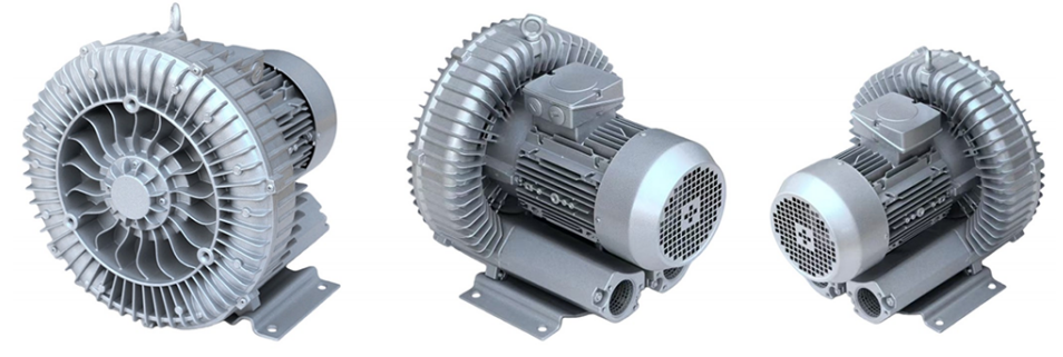
The illustrated blower uses a motor-driven impeller inside a ring-shaped flow housing. Air enters through the inlet, is repeatedly accelerated through the annular path, and leaves through the outlet at a higher pressure. In vacuum duty, the process connects to the suction side and the discharge is managed as the system exhaust. This makes the series suitable for equipment that needs continuous process airflow rather than short pulses of factory compressed air.
For an air-knife system, the blower is one part of a complete airflow circuit. Air-knife quantity, working length, outlet setting, pipe diameter, branch balance, filters, silencers, bends, and the required surface result all affect the operating point. Blower and air knife should therefore be matched as one system.
l Air-knife air supply: continuous airflow for drying, water removal, surface cleaning, and blow-off.
l Positive-pressure process air: airflow for manifolds, air curtains, cooling stations, and similar low-pressure duties.
l Vacuum service: suction airflow for extraction, pickup, hold-down, or transfer duties where the medium and filtration are suitable.
l Distributed airflow: one blower feeding several branches when the total simultaneous demand and branch resistance are properly calculated.
Treat the supplied ratings as clean-air reference data. Do not use the blower with flammable, explosive, corrosive, condensable, or heavily particle-laden media without a specifically validated configuration. Wet-process systems should prevent liquid carryover into the inlet, and all systems should include suitable pressure or vacuum protection.
A higher model suffix does not simply mean more airflow. Some variants hold airflow in a similar class while increasing pressure or vacuum capability; other families raise airflow while keeping the differential more moderate. The best model is the smallest configuration whose verified curve covers the required duty point with an appropriate engineering allowance.
Required duty | Family to shortlist | Why it may fit | Final check |
Compact 318/376 m3/h class | 2SG710-7AH06 / 16 / 26 / 37 | Several pressure and vacuum levels within one airflow class. | Use the exact curve and electrical row. |
420/500 m3/h, low-to-moderate resistance | 2SG730-7AH06 / 16 / 26 | Higher listed airflow than the 710 family. | Confirm pressure at required flow. |
320/380 m3/h, higher differential | 2SG720-7HH16 / 26 / 37 / 47 / 57 | Extends pressure and vacuum capability. | Check temperature, relief, and curve margin. |
500/600 m3/h, higher-volume duty | 2SG740-7GH37 / 47 / 57 | Highest airflow class in the supplied table. | Check the resistance at full system demand. |
Separate 320/370 m3/h option | 2SG790-7AH26 | Distinct performance and dimensional configuration. | Use its dedicated drawing and curve. |
Technical confirmation required | 2SG520-7HH46; 2SG710-7AA11 | Shown in drawings and curves, but absent from the rating table. | Obtain approved electrical and rating data. |
The supplied table lists 318 m3/h at 50 Hz and 376 m3/h at 60 Hz for the 7AH06, 7AH16, 7AH26, and 7AH37 variants. The series spans listed vacuum limits from -160 to -330 mbar and positive-pressure limits from 150 to 330 mbar, depending on model and frequency. It is a practical starting family when airflow is moderate and the primary decision is the differential needed to overcome system resistance.
The 7AH06, 7AH16, and 7AH26 variants are listed at 420 m3/h for 50 Hz and 500 m3/h for 60 Hz. They suit applications in which airflow is the main requirement and the connected system remains within the selected curve. The separately listed 2SG730-7AH37 shows 320/380 m3/h and higher differential capability; treat it as a distinct option and confirm its source data before quotation.
The 2SG720-7HH family remains in a listed airflow class of 320 m3/h at 50 Hz and 380 m3/h at 60 Hz while extending differential capability across HH16, HH26, HH37, HH47, and HH57. This family is the main shortlist when long pipe runs, narrow outlets, filters, multiple connected devices, or other restrictions raise total resistance. The highest supplied limits are -460 mbar vacuum and 660 mbar positive pressure, but available flow at those limits must be read from the curve.
The 7GH37, 7GH47, and 7GH57 models are listed at 500 m3/h for 50 Hz and 600 m3/h for 60 Hz. They are the first candidates when a process needs greater air volume and the required differential remains within the selected model curve. Select the suffix by the operating point, not by motor output alone.
The supplied row lists 320 m3/h at 50 Hz and 370 m3/h at 60 Hz. Listed maximum pressure is 200/250 mbar and listed maximum vacuum is -160/-240 mbar respectively. Use the dedicated drawing and performance curve to determine whether its duty and footprint suit the installation.
The 2SG520-7HH46 and 2SG710-7AA11 appear in the supplied dimensional drawing and performance chart but do not have complete rows in the supplied rating table. Keep them as technical-confirmation-required options until motor, electrical, airflow, differential, noise, and weight data are approved.
1. Define the operating mode. Choose positive-pressure delivery or vacuum service.
2. Define the duty point. State the airflow and the pressure or vacuum that must exist at that airflow.
3. Calculate total resistance. Include air knives, outlet settings, pipes, hoses, bends, branches, valves, filters, silencers, separators, and fixtures.
4. Choose the correct frequency. Use the 50 Hz graph for a 50 Hz supply and the 60 Hz graph for a 60 Hz supply; do not assume identical performance.
5. Locate the operating point. Select a curve that covers the required flow and differential with allowance for normal changes such as filter loading.
6. Check secondary limits. Confirm rated output, voltage, Delta / Star connection, current, noise, weight, footprint, port layout, and cooling space.
7. Confirm the complete configuration. Review the real piping, connected equipment, inlet-air condition, environment, controls, and protection before ordering.
Use the supplied curve sheet after defining the required duty point. The red curves represent vacuum operation and the blue curves represent positive-pressure operation. Always work from the frequency that matches the site supply.
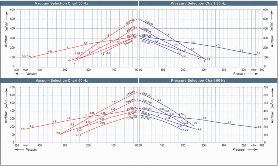
1. Choose the 50 Hz or 60 Hz chart that matches the electrical supply.
2. Use the vacuum side for suction duty or the pressure side for delivery duty.
3. Mark the required airflow on the vertical axis and the required differential on the horizontal axis.
4. Shortlist a curve that reaches the operating point with an appropriate margin for filter and pipe-condition changes.
5. Confirm the same model in the technical rating table, then verify voltage, current, noise, weight, and dimensions.
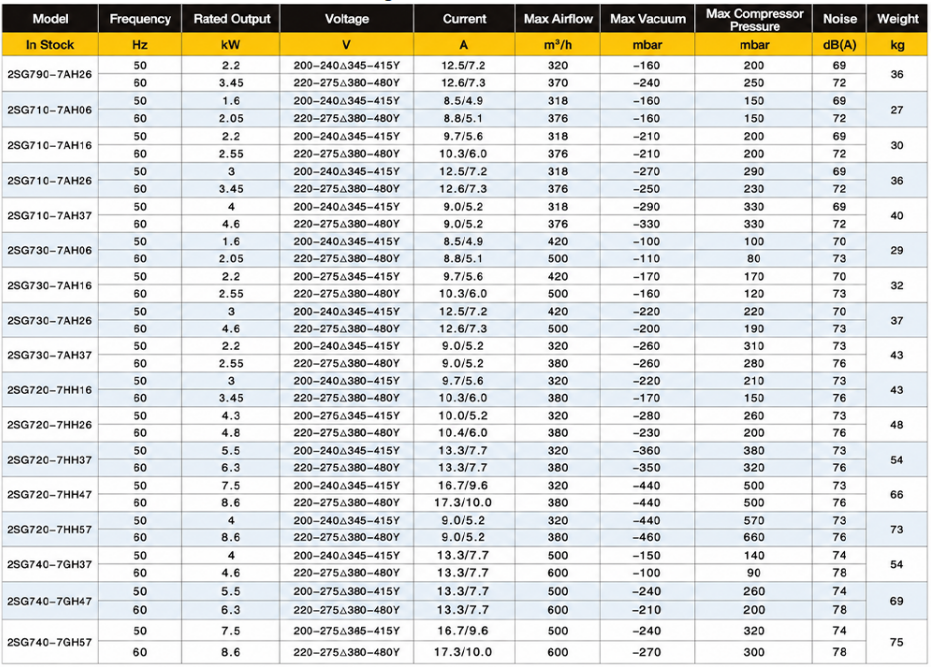
Use the model tables below for preliminary comparison after narrowing the range through duty-point selection. Values are transcribed from the supplied source table. Final electrical connection and permissible operating limits must follow the approved product data sheet and motor nameplate.
The supplied source table includes model-specific frequency, rated output, Delta / Star voltage, current, maximum airflow, maximum vacuum, maximum compressor pressure, noise, and weight. Insert the verified production asset below so customers can check the exact electrical row after selecting a model.
l Match site phase, frequency, voltage, and Delta / Star connection to the exact motor nameplate.
l Size switching, overload protection, cabling, and grounding from the approved current data and local requirements.
l Do not assume that a 50 Hz connection or current value applies at 60 Hz.
l If variable-speed operation is planned, obtain written confirmation of the permissible frequency range and cooling requirements.
Use the drawing sheet to compare representative footprints, base-hole positions, overall length, housing size, motor envelope, and connection locations. Never scale dimensions from the image. Confirm the exact model drawing before releasing a machine frame, guard, pipe layout, or acoustic enclosure.
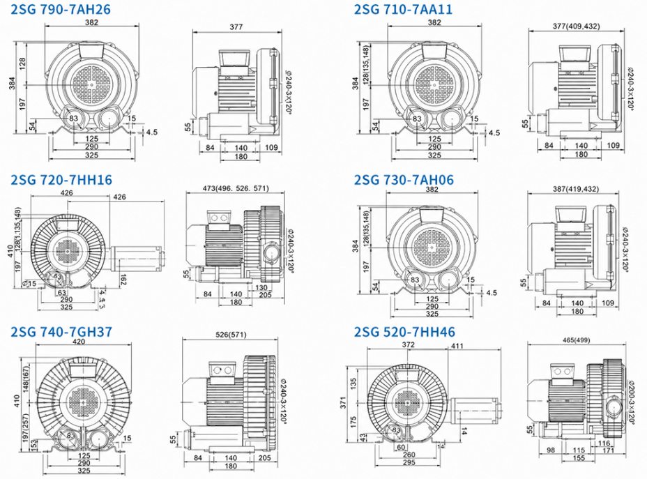
The supplied sheet shows 2SG790-7AH26, 2SG710-7AA11, 2SG720-7HH16, 2SG730-7AH06, 2SG740-7GH37, and 2SG520-7HH46. Some parenthetical lengths are variant-dependent. Obtain an approved drawing for any model not shown or whenever the selected motor and port configuration differs from the reference.
Mount the blower on a stable, level structure using the designated base holes. Confirm that the support carries blower weight, pipe loads, and operating vibration. Do not pull misaligned piping into the ports.
Keep runs as direct as practical, support pipes independently, and use a suitable flexible connection where movement or vibration isolation is required. Every bend, restriction, branch, filter, silencer, and terminal device changes the operating point.
Prevent dust, chips, liquid droplets, and process residue from entering the blower. Use filtration and, for wet processes, an appropriately sized separator or drainage arrangement. Removed water must not return through the blower pipe.
Provide limiting protection for the selected mode. Avoid prolonged operation with a blocked inlet or outlet. Maintain motor and blower ventilation, including when the unit is installed inside an acoustic enclosure.
Match voltage, frequency, current, phase, and Delta / Star connection to the approved nameplate. Qualified personnel should complete grounding, overload protection, and rotation checks in accordance with local requirements.
Verify rotation direction, airflow direction, pipe security, filter condition, leaks, vibration, sound, motor current, and actual system differential. Confirm that the measured operating point remains within the approved curve.
Inspect filtration, separators, pipe blockage, mounting hardware, unusual sound or vibration, motor current, and ventilation. Stop and isolate the equipment before inspection and allow hot surfaces to cool.
l Inlet filter selected for the process environment
l Liquid separator or moisture-control arrangement for wet duties
l Pressure-relief valve or vacuum breaker matched to the operating mode
l Silencer or acoustic treatment where the noise target requires it
l Flexible connector, independently supported piping, and suitable isolation valve
l Pressure or vacuum gauge for commissioning and maintenance checks
l Motor starter, overload protection, emergency stop, and approved controls
Start with the combined flow required by all air knives, then calculate pressure loss through pipes and branches. The 730 or 740 families are logical initial candidates for greater airflow; consider the 720 family when the air-knife array or pipe network creates higher resistance.
Confirm the airflow and impact required at the target surface, then account for air-knife geometry, outlet distance, line speed, and containment of removed material. Select filtration and collection measures appropriate to the contaminants.
For several outlets or branches, calculate total simultaneous airflow and the resistance of the least-favorable branch. Do not divide maximum free airflow equally without checking the complete network.
Start with the required suction flow at the process point and add losses through the intake line, filter, separator, and fixture. Shortlist from the vacuum side of the correct-frequency curve.
The 2SG Series provides a structured choice of airflow, pressure, vacuum, motor output, frequency, and installation size for industrial air systems. Customers can shortlist a model for positive-pressure supply or vacuum service, then confirm the final choice against the correct 50 Hz or 60 Hz performance curve and the resistance of the complete connected system.
Selection item | Supplied series range |
Operating modes | Positive pressure or vacuum |
Frequency | 50 Hz and 60 Hz |
Rated output | 1.6-8.6 kW across the supplied range |
Maximum airflow | 318-600 m3/h across the supplied range |
Listed vacuum limits | -100 to -460 mbar |
Listed positive-pressure limits | 80-660 mbar |
Listed noise | 69-78 dB(A) |
Listed weight | 27-75 kg |
Electrical data | Model-specific three-phase Delta / Star voltage and current values |
The illustrated blower uses a motor-driven impeller inside a ring-shaped flow housing. Air enters through the inlet, is repeatedly accelerated through the annular path, and leaves through the outlet at a higher pressure. In vacuum duty, the process connects to the suction side and the discharge is managed as the system exhaust. This makes the series suitable for equipment that needs continuous process airflow rather than short pulses of factory compressed air.
For an air-knife system, the blower is one part of a complete airflow circuit. Air-knife quantity, working length, outlet setting, pipe diameter, branch balance, filters, silencers, bends, and the required surface result all affect the operating point. Blower and air knife should therefore be matched as one system.
l Air-knife air supply: continuous airflow for drying, water removal, surface cleaning, and blow-off.
l Positive-pressure process air: airflow for manifolds, air curtains, cooling stations, and similar low-pressure duties.
l Vacuum service: suction airflow for extraction, pickup, hold-down, or transfer duties where the medium and filtration are suitable.
l Distributed airflow: one blower feeding several branches when the total simultaneous demand and branch resistance are properly calculated.
Treat the supplied ratings as clean-air reference data. Do not use the blower with flammable, explosive, corrosive, condensable, or heavily particle-laden media without a specifically validated configuration. Wet-process systems should prevent liquid carryover into the inlet, and all systems should include suitable pressure or vacuum protection.
A higher model suffix does not simply mean more airflow. Some variants hold airflow in a similar class while increasing pressure or vacuum capability; other families raise airflow while keeping the differential more moderate. The best model is the smallest configuration whose verified curve covers the required duty point with an appropriate engineering allowance.
Required duty | Family to shortlist | Why it may fit | Final check |
Compact 318/376 m3/h class | 2SG710-7AH06 / 16 / 26 / 37 | Several pressure and vacuum levels within one airflow class. | Use the exact curve and electrical row. |
420/500 m3/h, low-to-moderate resistance | 2SG730-7AH06 / 16 / 26 | Higher listed airflow than the 710 family. | Confirm pressure at required flow. |
320/380 m3/h, higher differential | 2SG720-7HH16 / 26 / 37 / 47 / 57 | Extends pressure and vacuum capability. | Check temperature, relief, and curve margin. |
500/600 m3/h, higher-volume duty | 2SG740-7GH37 / 47 / 57 | Highest airflow class in the supplied table. | Check the resistance at full system demand. |
Separate 320/370 m3/h option | 2SG790-7AH26 | Distinct performance and dimensional configuration. | Use its dedicated drawing and curve. |
Technical confirmation required | 2SG520-7HH46; 2SG710-7AA11 | Shown in drawings and curves, but absent from the rating table. | Obtain approved electrical and rating data. |
The supplied table lists 318 m3/h at 50 Hz and 376 m3/h at 60 Hz for the 7AH06, 7AH16, 7AH26, and 7AH37 variants. The series spans listed vacuum limits from -160 to -330 mbar and positive-pressure limits from 150 to 330 mbar, depending on model and frequency. It is a practical starting family when airflow is moderate and the primary decision is the differential needed to overcome system resistance.
The 7AH06, 7AH16, and 7AH26 variants are listed at 420 m3/h for 50 Hz and 500 m3/h for 60 Hz. They suit applications in which airflow is the main requirement and the connected system remains within the selected curve. The separately listed 2SG730-7AH37 shows 320/380 m3/h and higher differential capability; treat it as a distinct option and confirm its source data before quotation.
The 2SG720-7HH family remains in a listed airflow class of 320 m3/h at 50 Hz and 380 m3/h at 60 Hz while extending differential capability across HH16, HH26, HH37, HH47, and HH57. This family is the main shortlist when long pipe runs, narrow outlets, filters, multiple connected devices, or other restrictions raise total resistance. The highest supplied limits are -460 mbar vacuum and 660 mbar positive pressure, but available flow at those limits must be read from the curve.
The 7GH37, 7GH47, and 7GH57 models are listed at 500 m3/h for 50 Hz and 600 m3/h for 60 Hz. They are the first candidates when a process needs greater air volume and the required differential remains within the selected model curve. Select the suffix by the operating point, not by motor output alone.
The supplied row lists 320 m3/h at 50 Hz and 370 m3/h at 60 Hz. Listed maximum pressure is 200/250 mbar and listed maximum vacuum is -160/-240 mbar respectively. Use the dedicated drawing and performance curve to determine whether its duty and footprint suit the installation.
The 2SG520-7HH46 and 2SG710-7AA11 appear in the supplied dimensional drawing and performance chart but do not have complete rows in the supplied rating table. Keep them as technical-confirmation-required options until motor, electrical, airflow, differential, noise, and weight data are approved.
1. Define the operating mode. Choose positive-pressure delivery or vacuum service.
2. Define the duty point. State the airflow and the pressure or vacuum that must exist at that airflow.
3. Calculate total resistance. Include air knives, outlet settings, pipes, hoses, bends, branches, valves, filters, silencers, separators, and fixtures.
4. Choose the correct frequency. Use the 50 Hz graph for a 50 Hz supply and the 60 Hz graph for a 60 Hz supply; do not assume identical performance.
5. Locate the operating point. Select a curve that covers the required flow and differential with allowance for normal changes such as filter loading.
6. Check secondary limits. Confirm rated output, voltage, Delta / Star connection, current, noise, weight, footprint, port layout, and cooling space.
7. Confirm the complete configuration. Review the real piping, connected equipment, inlet-air condition, environment, controls, and protection before ordering.
Use the supplied curve sheet after defining the required duty point. The red curves represent vacuum operation and the blue curves represent positive-pressure operation. Always work from the frequency that matches the site supply.
1. Choose the 50 Hz or 60 Hz chart that matches the electrical supply.
2. Use the vacuum side for suction duty or the pressure side for delivery duty.
3. Mark the required airflow on the vertical axis and the required differential on the horizontal axis.
4. Shortlist a curve that reaches the operating point with an appropriate margin for filter and pipe-condition changes.
5. Confirm the same model in the technical rating table, then verify voltage, current, noise, weight, and dimensions.
Use the model tables below for preliminary comparison after narrowing the range through duty-point selection. Values are transcribed from the supplied source table. Final electrical connection and permissible operating limits must follow the approved product data sheet and motor nameplate.
The supplied source table includes model-specific frequency, rated output, Delta / Star voltage, current, maximum airflow, maximum vacuum, maximum compressor pressure, noise, and weight. Insert the verified production asset below so customers can check the exact electrical row after selecting a model.
l Match site phase, frequency, voltage, and Delta / Star connection to the exact motor nameplate.
l Size switching, overload protection, cabling, and grounding from the approved current data and local requirements.
l Do not assume that a 50 Hz connection or current value applies at 60 Hz.
l If variable-speed operation is planned, obtain written confirmation of the permissible frequency range and cooling requirements.
Use the drawing sheet to compare representative footprints, base-hole positions, overall length, housing size, motor envelope, and connection locations. Never scale dimensions from the image. Confirm the exact model drawing before releasing a machine frame, guard, pipe layout, or acoustic enclosure.
The supplied sheet shows 2SG790-7AH26, 2SG710-7AA11, 2SG720-7HH16, 2SG730-7AH06, 2SG740-7GH37, and 2SG520-7HH46. Some parenthetical lengths are variant-dependent. Obtain an approved drawing for any model not shown or whenever the selected motor and port configuration differs from the reference.
Mount the blower on a stable, level structure using the designated base holes. Confirm that the support carries blower weight, pipe loads, and operating vibration. Do not pull misaligned piping into the ports.
Keep runs as direct as practical, support pipes independently, and use a suitable flexible connection where movement or vibration isolation is required. Every bend, restriction, branch, filter, silencer, and terminal device changes the operating point.
Prevent dust, chips, liquid droplets, and process residue from entering the blower. Use filtration and, for wet processes, an appropriately sized separator or drainage arrangement. Removed water must not return through the blower pipe.
Provide limiting protection for the selected mode. Avoid prolonged operation with a blocked inlet or outlet. Maintain motor and blower ventilation, including when the unit is installed inside an acoustic enclosure.
Match voltage, frequency, current, phase, and Delta / Star connection to the approved nameplate. Qualified personnel should complete grounding, overload protection, and rotation checks in accordance with local requirements.
Verify rotation direction, airflow direction, pipe security, filter condition, leaks, vibration, sound, motor current, and actual system differential. Confirm that the measured operating point remains within the approved curve.
Inspect filtration, separators, pipe blockage, mounting hardware, unusual sound or vibration, motor current, and ventilation. Stop and isolate the equipment before inspection and allow hot surfaces to cool.
l Inlet filter selected for the process environment
l Liquid separator or moisture-control arrangement for wet duties
l Pressure-relief valve or vacuum breaker matched to the operating mode
l Silencer or acoustic treatment where the noise target requires it
l Flexible connector, independently supported piping, and suitable isolation valve
l Pressure or vacuum gauge for commissioning and maintenance checks
l Motor starter, overload protection, emergency stop, and approved controls
Start with the combined flow required by all air knives, then calculate pressure loss through pipes and branches. The 730 or 740 families are logical initial candidates for greater airflow; consider the 720 family when the air-knife array or pipe network creates higher resistance.
Confirm the airflow and impact required at the target surface, then account for air-knife geometry, outlet distance, line speed, and containment of removed material. Select filtration and collection measures appropriate to the contaminants.
For several outlets or branches, calculate total simultaneous airflow and the resistance of the least-favorable branch. Do not divide maximum free airflow equally without checking the complete network.
Start with the required suction flow at the process point and add losses through the intake line, filter, separator, and fixture. Shortlist from the vacuum side of the correct-frequency curve.


Shenzhen Qixingyuan Machinery Equipment Co., LTD.
info@airknifecn.com
Building 8, Wanfeng Third Industrial Zone, Xinqiao Street, Bao'an District, Shenzhen, Guangdong, China


