

A camera does not decide whether a surface looks clean to a person. It decides whether the pixels match a trained or programmed rule. A faint particle may create a sharp spot under directional light. A thin water film may move an edge, lower code contrast, or create glare. “Remove all dust” and “make the part dry” are not useful inspection specifications.
Ask what contamination can remain without changing the result. The answer depends on the defect, optics, lighting, pixel scale, algorithm, surface finish, and the cost of a wrong decision. An Air Knife can create a stable condition only when the cleaning target is tied to the vision task and tested on the line.
A person changes viewing angle and mentally ignores a loose fiber. A fixed camera sees the same fiber as a repeatable edge. Backlighting can make a particle opaque; dark-field light can make it flare. Coaxial light can turn a water droplet into a contrast change. The same contamination may be harmless in one setup and unacceptable in another.
A rule such as “no particles above 50 micrometers” says little unless resolution, magnification, focus, lighting, and the defect threshold are known. Height, reflectivity, position, color, motion blur, and location inside the region of interest also matter.
Start with the inspection requirement. If the vision system must reject a 0.20 mm scratch, then loose dust that produces an edge response similar to that scratch must be removed or reliably classified. If the task is only to confirm that a large cap is present, the same dust may not affect the decision at all.
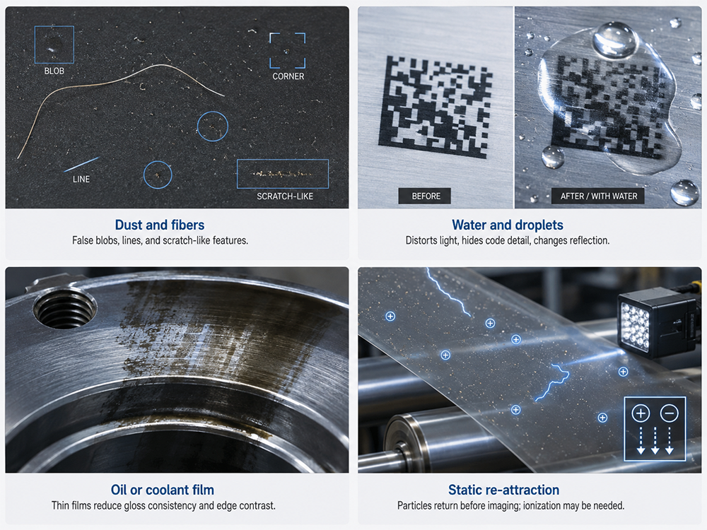
Dry particles appear as blobs, corners, lines, or texture. Fibers are troublesome in scratch inspection because their long edges resemble a real mark. Blow-off must move the particle out of the inspection area, not shift it elsewhere on the part.
A droplet can cover a code module, bend light, or create a bright ring. A continuous film changes reflection across a larger area. On polished metal, glass, and coated parts, the image may change before wetness is obvious. Judge dryness from image stability, not only by touch.
An air knife displaces free liquid but does not reliably remove bonded oil or dried residue. Oil can spread into a thin layer and still change gloss or edge contrast. Where washing or mechanical cleaning is needed, use the air knife as the final blow-off or drying step.
Plastic webs, films, and coated surfaces may hold a charge. Airflow removes a particle, then dust returns before imaging. Ionization and local extraction may be needed. More pressure alone can create a larger dust cloud.
The matrix below is a starting point for writing an acceptance rule. Each rule refers to what the camera measures. That makes it testable during commissioning and easier to maintain after a lens, light, recipe, or product finish changes.
Inspection task | How contamination appears | A practical “clean enough” rule |
Presence, position, or assembly check | A particle can become an extra blob; a droplet can hide an edge or shift a measured centroid. | No loose material in the region of interest that passes the same size, contrast, or shape filters used for the product feature. |
OCR and code reading | Water and oil change glare. Dust can cover character strokes or barcode modules. | The code region is dry and stable, and the lowest observed read margin remains above the production acceptance limit. |
Scratch, dent, and surface-defect inspection | Dust creates bright or dark points. Droplets and fibers produce edges that resemble scratches. | Particles and films must be below the smallest rejectable defect in image response, not only in physical size. |
Seal, bead, or adhesive inspection | Debris interrupts a contour. A wet film changes edge location and apparent bead width. | The measured contour stays inside tolerance on clean, intentionally borderline, and normal production samples. |
Color, gloss, or finish inspection | Thin oil or water films shift intensity and specular reflection over a broad area. | The surface is uniformly dry and free of visible film; intensity variation remains inside the calibrated process window. |
1. Define the smallest important defect or feature. Record its physical size, expected location, contrast, and inspection consequence. Separate cosmetic defects from safety, assembly, or traceability failures because the risk level is different.
2. Build a representative sample set. Include clean parts, normal production parts, known defects, and borderline contamination: single particles, fibers, fine droplets, streaks, and thin films where they realistically occur. Do not tune the system only with perfect samples.
3. Lock the imaging conditions before judging cleaning. Fix the camera position, lens, focus, aperture, exposure, light angle, light intensity, trigger timing, and part presentation. A moving lighting condition can look like a cleaning problem.
4. Measure the response with the same tools used in production. Useful outputs include blob area, edge strength, gray-level range, code grade or read confidence, measured width, classification score, and the distance from the pass/fail threshold.
5. Challenge the limit across the real operating window. Run at minimum and maximum conveyor speed, after warm-up, across shifts, and with expected product finish variation. Include air-supply variation and the widest or most difficult part position.
6. Write the acceptance rule and reaction plan. State what is checked, the sample frequency, the numeric or image-based limit, and what operators do after a failure. Keep a small set of approved reference images for setup and maintenance.
A short trial can hide dust buildup, loaded filters, blower warm-up, or conveyor vibration. Validate with repeated samples and track false rejects, missed defects, and decision margin over time. Run known defective parts through the full sequence; the jet must not move a component, flex a web, or alter a wet bead. Break results out by left, center, and right conveyor position so a weak airflow zone is not hidden by the average.
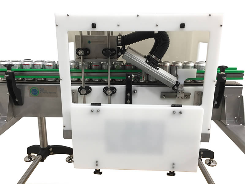
The best location is close enough to prevent recontamination, yet far enough from the camera for displaced dust and mist to leave the field of view. There is no fixed distance for every line. Product speed, enclosure airflow, particle settling, extraction position, and trigger delay all affect the answer. Blow away from the lens and illumination whenever the layout allows.
For many blower-driven drying applications, QXY uses a 20–50 mm knife-to-product distance and a 15°–45° impingement angle as practical starting ranges. The air jet is normally angled in the direction of conveyor travel so removed liquid has a clear path. These are setup starting points, not machine vision acceptance limits. Confirm the final distance and angle with image data.
QXY standard slot air knives are available with a 0.5–2 mm slot range and typically operate at 2–6 psi (0.14–0.42 bar) in blower-driven systems. A smaller gap can raise exit velocity but also changes flow demand and sensitivity to alignment. Do not adjust a factory-set slot casually. Check the full knife length with a feeler gauge and confirm that the blower still operates in its intended range.
A narrow weak zone can create a repeating band of false defects. QXY aluminum alloy air knives are factory calibrated for airflow uniformity of ±5% across the knife length. Standard lengths include 150, 300, 450, 600, 800, and 1000 mm, with custom lengths available. Knives longer than 600 mm normally use dual inlets to improve distribution. Duct branches still need to be balanced; equal-looking hose runs do not guarantee equal flow.
Blow-off without capture can relocate the problem. Use guards, a collection tray, or local extraction where dust or mist would otherwise circulate. Keep the camera window outside the direct plume. Filter the supply air when oil, water, or particles from the air source could land on the product. For static-sensitive surfaces, place ionization so neutralization occurs before or during blow-off and verify that the ionizer does not disturb the image.
Recesses, holes, and complex profiles can shelter contamination from a straight air sheet. A small-hole air knife can target PCB through-holes; a tornado air knife suits recessed or 3D parts; dual-sided knives treat both faces of a flat product. Match material to the process environment: stainless steel near corrosive cleaners or washdown, PVC near controlled-temperature acid or alkaline processes, and aluminum alloy in dry general industrial positions.
Bonded grease, cured residue, tacky dust, and embedded particles need washing, brushing, vacuum, or another first-stage process. The air knife can then remove free liquid and standardize the final condition before imaging.
• Run a clean reference part repeatedly and confirm that the image baseline does not drift after the air knife starts.
• Seed realistic contamination at the center and both edges. Verify removal without moving the part or damaging the surface.
• Check the camera window and light after an extended run for mist, dust, or droplets carried by the plume.
• Compare the first part after startup with parts produced after thermal and airflow conditions stabilize.
• Record pressure or blower condition at the knife inlet, not only at the source. Inspect filters and ducts as part of the test.
• Repeat the test at the fastest line speed and shortest spacing between parts.
• Save accepted and rejected images with the setup record so future maintenance can reproduce the same condition.
The final target is repeatability. A surface does not need to be laboratory-clean if the remaining contamination cannot affect the inspection decision. It may need to be much cleaner than it looks when the system is searching for small, low-contrast defects. The sample study tells you which case you have.
For cleaning before machine vision, relevant options include aluminum alloy slot air knives for open surfaces, small-hole air knives for PCB through-holes, tornado air knives for recessed or complex parts, air-to-air systems for two-sided products, and stainless steel or PVC designs for demanding process environments. QXY Machinery can provide custom lengths, slot widths, hole patterns, and inlet configurations to suit conveyor width and product geometry.
QXY Machinery combines in-house engineering, production, sales, and application support. The correct specification should be based on the contamination, inspection width, product shape, line speed, available air source, and the image-based acceptance test.
→ Contact QXY Machinery to discuss an air knife setup for cleaning before machine vision inspection.
FAQ
Q: How clean must a part be before machine vision inspection?
A: Clean enough means remaining dust, liquid, or film cannot push the inspection result across its pass/fail threshold. Define the limit with representative samples and the actual camera, lighting, and algorithm. There is no single particle-size limit for every vision system.
Q: Can an air knife eliminate machine vision false rejects?
A: It can reduce false rejects caused by loose dust, droplets, and free liquid. It will not correct unstable lighting, poor fixturing, lens contamination, weak algorithms, or bonded residue. Use image records to separate cleaning faults from vision faults.
Q: Should the air knife be installed immediately before the camera?
A: Usually it should be close enough to limit recontamination, but not so close that dust or mist enters the image or coats the optics. Set the distance from product speed, extraction, enclosure airflow, and the time needed for the part to become stable.
Q: What air knife distance and angle should be tested first?
A: For many blower-driven surface applications, a 20–50 mm distance and a 15°–45° angle from the surface are useful starting ranges. Final settings must be verified on the actual part at production speed.
Q: Is more air pressure always better before optical inspection?
A: No. Excess airflow can move thin parts, spread oil, atomize liquid, raise dust, or contaminate the camera window. Use the lowest stable setting that meets the image-based cleanliness limit across the full inspection width.
Q: Do I need ionized air for dust removal before machine vision?
A: Consider ionization when plastic, film, or coated surfaces attract particles again after blow-off. Test charge neutralization together with extraction and confirm that the added equipment does not change part position or image stability.
Q: How should cleanliness performance be monitored after commissioning?
A: Track false rejects, known-defect detection, decision margin, and results by conveyor position. Add routine checks for the air knife slot, inlet condition, filters, ducts, extraction, and camera window. Keep approved reference images for comparison.
Need a custom air knife solution? Send us your application details, material requirement ,or air source type . Our engineering team will help you select the right model.

Shenzhen Qixingyuan Machinery Equipment Co., LTD.
info@airknifecn.com
Building 8, Wanfeng Third Industrial Zone, Xinqiao Street, Bao'an District, Shenzhen, Guangdong, China


