 English
 Español
  Português
  русский
  Français
  日本語
日本語  Deutsch
  tiếng Việt
  Italiano
  Nederlands
  ภาษาไทย
  Polski
  한국어
한국어  Svenska
  magyar
  Malay
Malay  বাংলা ভাষার
  Dansk
Dansk  Suomi
Suomi  हिन्दी
  Pilipino
  Türkçe
  Gaeilge
  العربية
  Indonesia
  Norsk
Norsk  تمل
تمل  český
český  ελληνικά
  український
  Javanese
  فارسی
فارسی  தமிழ்
தமிழ்  తెలుగు
  नेपाली
  Burmese
  български
  ລາວ
ລາວ  Latine
  Қазақша
  Euskal
  Azərbaycan
  Slovenský jazyk
  Македонски
  Lietuvos
  Eesti Keel
  Română
  Slovenski


Simulation and Theoretical Research on the Air Knife Structure of Coating Oven
2023-03-23
Simulation and Theoretical Research on the Air Knife Structure of Coating Oven
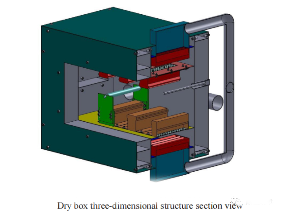
The air knife is the key design link and executive element of the drying box. Its structure type directly affects the distribution of the air flow field inside the drying box and the drying effect of the pole piece slurry layer. It plays a role in organizing the airflow in the drying box and adjusting The function of the airflow and the reasonable structure type can avoid the vortex of the airflow, so that the airflow can be blown slowly and evenly to the surface of the pole piece. At the same time, the air knife is a resistance element, and the resistance of the air knife is large, which will increase the resistance of the entire drying box, thereby increasing the energy loss of the drying system. In addition, a perforated screen can be installed inside the air knife, which plays a role in evenly distributing the flow of hot air flowing in from the air chamber.
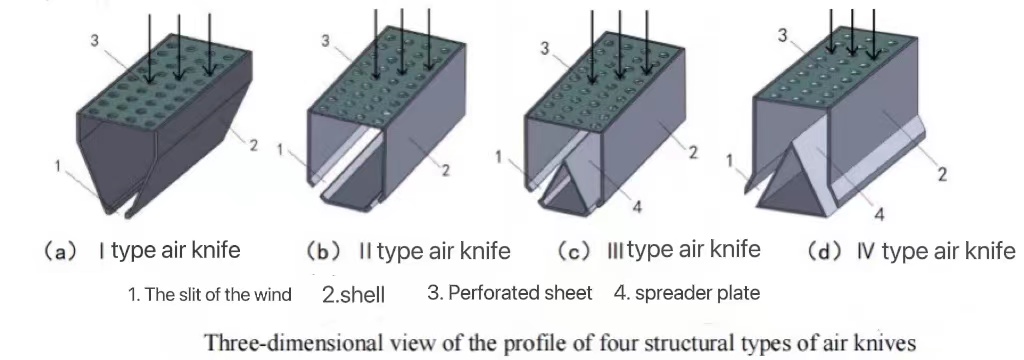
The figure above shows the structure of 4 types of air knives given in this paper. In the type I air knife in (a), the air flow is blown out from the bottom tuyere slit after the cavity of the inverted triangular section is adjusted; in the type II air knife in (b), the air flow is adjusted in the cavity of the rectangular cross section and passes through The two sides of the bottom are blown out obliquely to the slits of the air nozzle; the type III air knife in (c) constructs an inner cavity dividing plate on the basis of the type II air knife, and the air flow passes through the two sides of the bottom under the drainage of the dividing plate. Blow out from the slit of the oblique air nozzle; for the type IV air knife in (d), on the basis of the type III air knife, the shape of the air knife shell is changed, and the outward convex is changed to the inward concave. This type of air knife is a process in which high-speed hot air flow is generated at the exit of the air nozzle slit, and then the surface of the pole piece is impacted and dried, and the air convective heat transfer is carried out, and the solvent molecules of the slurry layer are carried away.
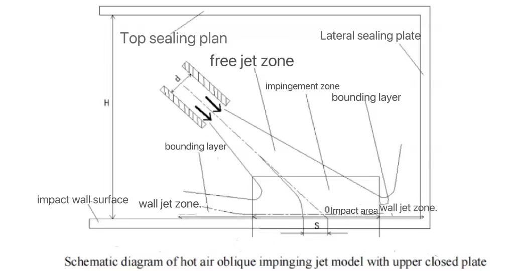
As shown in the figure, H is the height of the drying area of the drying box, d is the width of the air knife slit, and the center line of the impact jet forms a certain angle with the impact wall. The impingement jet can be divided into free jet zone, impingement zone and wall jet zone.
Free jet zone: The characteristic of the free jet zone is that the velocity of the hot air at any position in this zone is the same as the velocity of the airflow at the tuyere, and the airflow keeps the original impact potential energy unchanged. Since the injected thermals initially exchange momentum with the stationary fluid in the surrounding environment, the area width of the injection increases as the free jet continues.
Impact zone: After the free jet is over, the flow velocity of the hot air will also change accordingly, from a uniform distribution at the beginning to a gradual decrease. During this process, the lateral width of the jet zone continues to expand, forming an impact zone. In the impact zone, it can be found that the thickness of the boundary layer above the impact wall is almost the same.
Wall jet area: After the airflow reaches the impact wall, the direction of the airflow is turned at a certain angle and enters the wall jet area. The airflow in this area flows close to the wall surface, and the velocity value decreases as the flow progresses.
Comparative analysis of hot air flow trace diagrams
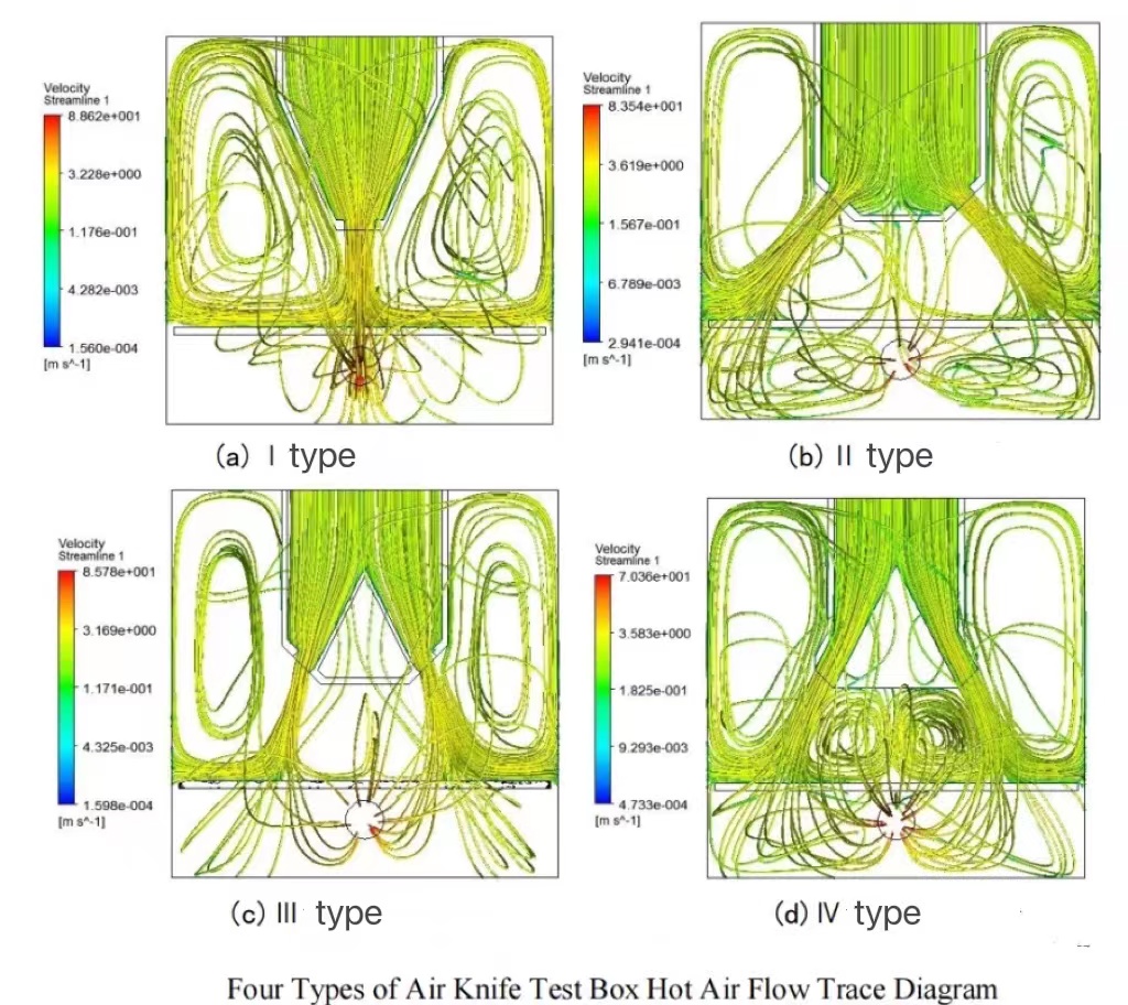
Disordered hot air enters the air knife from the air inlet, passes through the uniform flow of the perforated mesh plate and the distribution of the distribution plate, and the hot air flows evenly to the air nozzle of the air knife. When the hot air reaches the pole piece, changing the flow direction produces the result shown in the figure below. The uniformity of the hot air blowing on the pole piece is mainly controlled by two parts, one is the uniform flow mesh to make the hot air evenly enter the air knife, and the other is the air knife's nozzle to the hot air again.
The four types of test box trace diagrams are different because of the different types of air knives.
The distribution of hot air flow traces in the I-type air knife test box is relatively regular. On the surface of the pole piece, the hot air flows from the middle to the two ends and the upper space, basically covering the surface of the pole piece;
The distribution of hot air flow traces in the type II air knife test box is relatively scattered. On the surface of the pole piece, most of the hot air particles flow only to the upper space from the two ends of the pole piece, and the coverage area is small;
Most of the hot air particles in the type III air knife test box flow from the two sides (not both ends) of the middle of the pole piece surface to the two ends and the upper space, covering a large area; The position flows to the middle, both ends and the upper space of the pole piece at the same time, and the distribution is relatively symmetrical and uniform, basically covering the surface of the pole piece.


X
We use cookies to offer you a better browsing experience, analyze site traffic and personalize content. By using this site, you agree to our use of cookies.
Privacy Policy